Le web intelligent

Dernière mise à jour: 19 mars 2017

Chronologie Internet

Il y a presque 4 ans, j’avais publié sur mon blog une proposition de diviser la chronologie du web (timeline) en neuf époques. J’avais opté pour le nom de web intelligent (web 3.5) pour caractériser la période de début 2015 à mi 2017.

Pour moi, le web intelligent a les compétences suivantes:

  • il parle notre langue
  • il lit notre écriture
  • il comprend notre langage et reconnaît notre voix
  • il reconnaît notre visage et décode nos émotions
  • il interprète des images et scènes vidéo
  • il a des connaissances vastes sur tous les sujets
  • il prend des décisions autonomes
  • il est capable d’apprendre afin de parfaire ses compétences

Les technologies qui sont à la base de ces compétences existent depuis des années, voire des décennies. Ils ont fait l’objet de recherches, de  tests, de prototypes, d’applications innovantes et de produits commerciaux, mais le plus souvent d’une façon isolée, pour une seule compétence.

Le GPS nous parle dans la voiture, Siri et Alexa répondent à nos questions sur le mobile, Google Photo et Facebook reconnaissent les visages sur nos photos, Wikipedia sait tout (ou presque), des outils d’aide à la décision sont omniprésents et les réseaux neuraux permettent aux machines d’apprendre en profondeur (deep learning).

Ce qui a changé en 2016, c’est le fait que toutes ces technologies ont été assemblées par Google et par Amazon Web Services (AWS) dans des produits commerciaux d’intelligence artificielle qui sont maintenant à la disposition des développeurs du monde entier.

Le web 3.5 est donc devenu réalité.

Google Cloud Platform

Google est bien connu pour son moteur de recherche, sa plateforme vidéo Youtube et ses services de traduction. Depuis 2011, Google offre aux programmeurs et sociétés d’héberger leurs propres applications sur la même infrastructure que celle qu’elle utilise en interne. Ce service est appelé Google Cloud Platform et se compose d’une famille de produits, chacun comportant une interface web, un outil de lignes de commande, et une interface de programmation applicative REST. Parmi ces produits on distingue:

  • Google App Engine
  • Google Storage
  • Goggle Compute Engine
  • Google Translate

L’ensemble des produits et services est décrit sur la page web cloud.google.com.

En mars 2016, Google a annoncé le lancement de la famille Cloud Machine Learning service mainstream. Les services suivants font partie, entre autres, de cette famille:

  • Cloud ML : Large Scale Machine Learning Service
  • Cloud Natural Language API : Powerful Text Analysis
  • Cloud Speech API : Powerful Speech Recognition in 80 languages
  • Cloud Translate API : Fast, Dynamic Translation
  • Cloud Vision API : Powerful Image Analysis

Google Cloud Vision

De prime abord, je me suis intéressé pour le nouveau service Cloud Vision. Dans le passé j’avais déjà effectué des tests avec différentes applications de reconnaissance faciale et de lecture de textes. Les contributions afférentes sont disponibles sur mon blog.

Pour faire des tests, j’ai pris au hasard quelques photos de mes petits-enfants.

Les résultats de Google Vision sont affichés dans plusieurs onglets:

  • Faces : reconnaissance de visages et d’émotions
  • Labels : reconnaissance de scènes et d’objets
  • Text : lecture de caractères et de textes
  • Colors : classification des couleurs dominantes
  • Safe Search : contenus avec nudité, violence, haine ou sujets médicaux
  • JSON Response : ensemble détaillé des données en format JSON

Les résultats ont été assemblés dans une seule image, par copie-collage, pour donner une meilleure vue globale.

Google Vision ne fournit pas un service de reconnaissance des personnes comme dans Google Photo, mais se limite à détecter les visages et à interpréter les émotions. Dans la figure ci-dessus les informations pour les deux visages sont indiquées en haut à droite (Charles) et en bas à gauche (Capucine). Les étiquettes (label)  pour la scène sont affichées en bas au milieu, le texte reconnu se trouve en bas à droite.

Les termes reconnus “Carla” et “Charlie” sont les noms de vaches qui figurent sur la nappe de la table, comme on peut le voir sur l’agrandissement ci-dessous.

Un exemple de l’onglet “JSON Response” est présenté ci-après. Tous les détails de l’analyse sont fournis dans cette structure JSON.

En ce qui concerne l’analyse proprement dite, Google Vision ne détecte pas d’émotions sur les visages des deux enfants, sauf une légère surprise sur le visage de Charles. Hormis la reconnaissance de personnes (toddler, child),  Il n’y a guère d’informations sur le contexte.

Pour les images suivantes, seuls les résultats “Faces” et “Labels” sont présentés dans les figures montées.
 Google Vision voit de la joie dans le visage de Charles qui se trouve dehors, dans une sorte de jardin, avec des feuilles, en automne. Bonne interprétation.
 Google Vision estime que Charles fête son anniversaire à Noël. En réalité il joue en février 2016 avec du Lego. Echec.
L’activity-Center Fisher-Prize de Thomas fait penser Google Vision à un anniversaire et à de la nourriture.

Google Vision considère que Thomas est un peu surpris et combine les activités jouer et manger. Bien.

Thomas semble être en colère et se trouve dans la neige, en hiver et il a froid. Analyse correcte.

Amazon Web Services

Tout le monde connaît Amazon en tant que fournisseur en ligne de livres et d’autres objets non périssables, mais peu de personnes savent que Amazon est un des plus grand fournisseurs mondiaux de services informatiques sous le nom de Amazon Web Services (AWS). Tout comme Google, Amazon profite de l’infrastructure nécessaire pour ses propres besoins pour offrir de la capacité et des services à des tiers. Lancé en 2006, AWS se classe aujourd’hui au premier rang des fournisseurs Cloud avec une part de marché de 31%, devant Microsoft (11%) et IBM (7%).

J’utilise les services d’AWS depuis octobre 2008.

Le 30 novembre 2016, Werner Vogels, le CTO (Chief Technological Officer) de Amazon, annonçait sur son blog All Things Distributed le lancement des nouveaux services d’intelligence artificielle (AmazonAI) de AWS.

Amazon AI

Le but d’Amazon AI est d’apporter une intelligence artificielle puissante à tous les développeurs. La gamme des services Amazon AI se compose de:

  • Amazon Lex : concevoir des interfaces conversationnelles ayant recours à la voix et au texte, via les mêmes technologies d’apprentissage approfondi que celles utilisées par Alexa
  • Amazon Rekognition : reconnaissance d’image basée sur l’apprentissage approfondi
  • Amazon Polly : convertir un texte en voix numérique
  • Amazon Machine Learning : un service d’apprentissage automatique évolutif pour les développeurs

Chez Amazon AI, je me suis également intéressé d’abord pour Amazon Rekognition. Du premier coup j’ai vu des ressemblances avec la technologie Orbeus ReKognition que j’avais exploré en 2014. Dans la suite j’ai trouvé sur le net un article de Bloomberg relatant que Amazon a acquis en automne 2015  la startup Orbeus Inc., mais sans en faire une annonce officielle.

Amazon Rekognition ne fournit pas seulement des informations sur les émotions détectées sur les visages, mais également des renseignements sur le sexe et sur des accessoires comme lunettes, barbes, moustaches. Dans la détection des scènes et objets on reçoit en général plus d’étiquettes qu’avec Google Vision. Amazon Rekognition n’offre toutefois pas une reconnaissance intégrée de textes.

Les résultats des tests effectués avec les mêmes six photos de mes petits-enfants sont présentés ci-après. On peut donc les comparer avec ceux fournis par Google Vision.

Charles est identifié comme une fille, ce qui n’est pas correct. Le décor est reconnu correctement comme maison et même le Dudu de Capucine est associé correctement à une courtepointe (quilt, towel).

La scène est considérée comme un labyrinthe, une arène ou un amphithéâtre. Il n’y a pas de notion de nature ou de bois.  Google a fait mieux. Amazon AI est toutefois d’accord avec Google Vision que Charles sourit.

Le système reconnaît des personnes, des jouets, une chaise et un coussin dans un décor de maison. Il confond toutefois des jouets avec de la nourriture. Google Vision n’a pas fait mieux.

Le centre d’activités Fisher-Price de Thomas est identifié comme un gâteau d’anniversaire, ou un dessert, en tout cas quelque chose pour manger. Google Vision a fait les mêmes réflexions.

Dans cette scène, le système détecte correctement qu’il s’agit d’objets pour boire et manger. Thomas, plus âgé que sur la précédente photo, est reconnu maintenant comme un garçon qui ne rit pas, mais qui paraît surpris.

La scène n’est pas reconnue comme activité dans la neige et le système interprète le pleur de Thomas comme un grand sourire. Echec complet.

Amazon Face Comparison

Le service Amazon Rekognition comprend l’application Face Comparison (comparaison faciale) qui est très performante. A partir d’une photo avec un visage de référence, le service Face Comparison fournit des taux de ressemblance des visages qui figurent sur une photo de comparaison. La série des figures ci-dessous montre quelques exemples:

Thomas est reconnu avec une fiabilité de 93%; similitude avec Charles (83%) et Capucine (76%).

Charles n’est pas reconnu, mais il y a similitude de 74,9% avec Thomas et de 55,1% avec Capucine.

Capucine est reconnue avec une fiabilité de 91%. Il n’y a pas de ressemblance avec les autres.

Marco est reconnu avec une fiabilité de 92%. Il n’y a pas de similitude détectée avec les enfants.

Astor, qui ne figure pas sur la photo à droite, ne ressemble à personne sur cette photo

Amazon fournit également un service de reconnaissance faciale. Il s’agit d’un processus d’identification et de vérification de l’identité d’une personne, en recherchant son visage dans un répertoire d’images de visages. Un répertoire d’images de visages est un index de recherche de vecteurs de caractéristiques faciales. AWS offre plusieurs interfaces (API) pour gérer un tel répertoire et pour ajouter ou supprimer des visages de référence dans le répertoire.

En ce temps Google Vision ne supporte pas encore la reconnaissance des visages dans son API public. Il n’y a donc pas moyen de comparer les performances avec Amazon Rekognition.

Dessins de Capucine

Pour pousser Google Vision et Amazon Rekognition aux limites, j’ai soumis deux dessins récents de ma petite-fille Capucine (4 ans et demi) et une des premières ébauches d’écriture de son nom aux deux systèmes.

Dessins et texte de Capucine à l’âge de 4 ans et demi

Les résultats fournis par Google Vision et Amazon Rekognition ont été assemblés chaque fois dans une seule image.

Le dessin du bonhomme est reconnu par Google Vision (résultats au milieu) comme cartoon et oeuvre d’art, tandis que Amazon Rekognition voit une signature ou un insecte. Aucun des deux systèmes reconnaît une figure humaine.
Les visages avec des boucles d’oreille qui ornent le contour de la main de Capucine ne sont pas identifiés comme tels par aucun des systèmes. Ce sont des lignes, des dessins, des formes ou diagrammes. Amazon Rekognition est au moins d’avis qu’il s’agit de l’art.
En ce qui concerne le nom de Capucine, Google Vision estime qu’il s’agit d’un texte, mais n’est pas en mesure de le lire. L’OCR (optical character recognition) ne fait pas encore partie du produit Amazon Rekognition. Ce système détecte toutefois qu’il s’agit de textes, de caractères, d’une signature ou d’un autographe.

Conclusions

Les performances des deux systèmes Google Vision et Amazon Rekognition sont impressionnantes. Globalement Google Vision semble être plus fiable dans ses analyses en comparaison avec Amazon Rekognition, abstraction faite de la reconnaissance faciale d’Amazon qui est unique.

Bien sûr il y a encore un besoin d’amélioration pour les deux systèmes. Les services Machine Learning des deux fournisseurs permettent de mieux adapter la reconnaissance d’objets et de scènes à son propre environnement, en formant les systèmes moyennant un échantillon d’images et de photos d’apprentissage, avec des étiquettes (labels) sélectionnées manuellement et des étiquettes corrigées en cas d’erreur.

Google profite d’ailleurs sur son site de démonstration d’une variante de son système reCAPTCHA pour exclure les robots à l’utilisation de sa plateforme Cloud. Les réponses fournies par les humains sont utilisées pour parfaire Google Vision.

Google CAPTCHA: Completely Automated Public Turing test to tell Computers and Humans Apart

Le loup et les trois cochons

Le loup

Le loup est un animal, mais le terme loup ne correspond pas à un niveau précis de la classification scientifique des espèces. Dans la présente contribution nous nous intéressons au loup dans sa qualité de personnage traditionnel de conte qui apparaît dans plusieurs récits folkloriques.

Parmi les contes les plus anciens les fables d’Esope sont les mieux documentées. Les fables d’Esope relatives au loup sont:

Le loup et le héron

Les fables d’Ésope ont inspiré de nombreux auteurs.

Les contes des frères Grimm (Grimms Märchen) sont un autre exemple de récits qui se focalisent sur le loup:

Lors du bicentenaire de la publication des contes des frères Grimm le 20 décembre 2012,  Google a dédié un doodle en hommage aux auteurs.

Grand méchant loup

Dans les contes, le loup est vu comme un personnage cruel. Il est là pour faire peur et terroriser ses futures proies. En effet, il se régale des enfants égarés, des grands-mères, mais aussi des animaux plus faibles que lui. Les contes renforcent la mauvaise image que le loup colportait à l’époque où ils furent écrits, c’est-à-dire entre le XVIIe siècle et le XIXe siècle. Le loup était vu par l’homme comme un prédateur, qui pouvait s’attaquer à l’homme à n’importe quel moment.

C’est pour ces raisons que les termes Grand-méchant Loup ou Grand Loup ont fait leur apparition il y a plus de 100 ans.

Les trois cochons

Les Trois Petits Cochons est un conte traditionnel européen dont les premières versions imprimées datent de 1840, bien que son origine puisse remonter plus loin. Le conte mets en scène trois jeunes cochons et un loup. Les trois petits cochons veulent vivre leur vie et quittent le foyer familial pour tenter leur chance dans le monde. Le premier petit cochon se construit une maison de paille. Le deuxième petit cochon se construit une maison faite de bois. Le troisième petit cochon se construit une maison de briques et de ciment.

Le grand méchant loup parvient à détruire les maisons des deux premiers petits cochons en soufflant dessus et les dévore. En revanche, il est impuissant contre celle du troisième petit cochon.

Pour le faire sortir de sa maison, le loup lui propose d’aller chercher des navets avec lui. Mais le cochon sort tôt le matin et rentre chez lui avec les navets avant l’arrivée du loup. Le loup retente sa chance et propose au cochon d’aller cueillir des pommes. Le cochon part à nouveau avant l’heure, mais ayant eu du mal à grimper à l’arbre, le loup arrive à son tour. Le cochon lance alors une pomme très loin en proposant au loup de la goûter. Pendant que le loup la ramasse, il se sauve. Le loup persévère et propose au cochon d’aller à la foire. Arrivé le premier à la foire, le cochon achète une baratte. Sur le chemin du retour, il voit venir le loup : il se cache alors dans la baratte et dévale la pente, ce qui fait peur au loup.

Ce dernier retourne à la maison du petit cochon et découvre que c’est le petit cochon qui lui a fait peur. En colère, il décide de rentrer par la cheminée pour dévorer le cochon. Mais il tombe dans une marmite de soupe bouillante et le cochon le mange pour son dîner.

Ce récit a été illustré par Leonard Leslie Brooke, un dessinateur et écrivain anglais (1862 – 1940), dans une édition de 1904 The Story of the Three Little Pigs, qui est disponible sur le site web de Project Gutenberg.

Illustration des trois petits cochons par L. Leslie Brooke

Le récit est devenu célèbre grâce aux Studios Walt Disney qui ont fait des trois petits cochons les héros de courts métrages animés de la série Silly Symphonies.

Silly Symphonies

Les Silly Symphonies sont une série de courts métrages animés produits entre 1929 et 1939 par les studios Disney. Quelques personnages récurrents dans cette série sont les Trois Petits Cochons.  C’est d’ailleurs le nom du premier court métrage d’animation (Three Little Pigs) de ces personnages, produit par les studios Disney en 1933. Il est basé sur le conte folklorique Les Trois Petits Cochons et a été réalisé par Burton Gillett.

Silly Symphonies – Three Little Pigs

Les studios concurrents de Disney, Warner Bros., se sont directement inspirés du concept Silly Symphonies de Disney pour créer Looney Tunes et Merrie Melodies.

Three Little Pigs – 1933

Les trois petits cochons Nif-Nif (Fiddler Pig),  Nouf-Nouf (Fifer Pig) et Naf-Naf (Practical Pig) construisent respectivement des maisons de paille, de bois et de briques. Le grand méchant loup détruit en soufflant les deux premières avant de se heurter à la solidité de la troisième dans laquelle se sont réfugiés les trois cochons, il souffle encore jusqu’à en perdre son pantalon. Il tente alors de s’introduire par la cheminée mais Naf-Naf, le plus sage des petits cochons, l’ayant entendu, ajoute de la térébenthine dans une grande marmite d’eau bouillante. Le loup descend et tombe dans la marmite avec l’eau bouillante ; de douleur il crie, saute et s’enfuit dans la forêt, traînant son derrière au sol en hurlant tandis que les petits cochons sauvés rient de cette infortune.

Sur le mur de la maison de pierre on peut apercevoir les portraits de la mère (Mother) et du père (Father) des trois petits cochons, représentant respectivement une truie allaitant sept porcelets et un chapelet de saucisses.

Le film a reçu en 1934 un Oscar pour le meilleur court-métrage d’animation.

Le loup souffle la maison en paille

Le loup se déguise en mouton

Le loup se déguise en vendeur de brosses juif

Version censurée du loup déguisé en vendeur de brosses

Les trois cochons fêtent la fuite du loup

The Big Bad Wolf – 1934

Sorti en 1934, le film Le grand méchant loup est la suite des trois petits cochons. Il est basé sur le conte de tradition orale Le Petit Chaperon Rouge. Il a été réalisé également par Buron Gillet. L’histoire est la suivante:

Le petit chaperon rouge rencontre les trois petits cochons sur le chemin la menant à la maison de sa grand-mère. Naf-Naf, le cochon pratique, préfereait prendre le long chemin pour éviter les bois mais le reste de la troupe préfère prendre le raccourci, boisé. Surgi alors le Grand Méchant Loup. Les cochons s’enfuient et abandonnent le petit chaperon rouge. Le loup la poursuit jusqu’à la maison de la grand-mère. Il parvient à les enfermer dans la garde-robe en vue de les manger. Heureusement, le cochon pratique arrive et met du pop-corn et des braises brûlantes dans le pantalon du loup qui s’enfuit en hurlant. La grand-mère et le petit chaperon rouge sont sauvées.

Le Grand Méchant Loup et le Chaperon Rouge

Three Little Wolfes – 1936

La troisième épisode avec les trois cochons a été réalisée en 1936 par David Hand. Le grand méchant loup apprend à ses trois petits loups les bases de leur nourriture et de la cuisine, principalement du cochon.

Dans la famille des caractères de Disney, le Grand Loup est le seul à avoir des enfants, et non des neveux, comme les autres figures.

Du côté des cochons, Naf-Naf finit l’installation du Pacificateur de loup tandis que les deux autres petits cochons jouent à crier au loup sur leur frère. Mais le loup arrive déguisé, capture les deux joueurs et les enferme dans sa maison.

Finalement Naf-Naf va au secours de ses frères et réussit à introduire le loup dans la machine de pacification où il est maltraité.

The Practical Pig – 1939

Le Cochon Pratique est la dernière épisode des Silly Symphonies avec les trois cochons; elle a été réalisée en 1939 par Dick Rickard.

Le loup se déguise en sirène pour attraper Nif-Nif et Nouf-Nouf lors d’une baignade. Il les mène à la maison où les louveteaux attendent avec impatience le déjeuner. Le loup veut partir d’abord chercher Naf-Naf et il commande à ses enfants de ne pas commencer à manger avant son retour. Malgré ces instructions, les jeunes loups commencent à préparer un plat avec les deux cochons qui leur rappellent qu’il faut obéir à son père.

Le loup se déguise en facteur des postes et fournit un faux message à Naf-Naf qui réussit à l’introduire dans un détecteur de mensonges. Nif-Nif et Nouf-Nouf arrivent à s’échapper et à retourner à la maison de Naf-Naf, le cochon pratique. A la fin le loup est lancé avec une fusée dans les nuages.

The Practical Pig

The Thrifty Pig – 1941

The Thrifty Pig (le cochon économe) est le premier court métrage d’animation américain réalisé par Walt Disney Productions en coopération avec le Department of National Defense et l’Office National du Film du Canada, sorti aux États-Unis et au Canada le 19 novembre 1941.

Il s’agit d’un remake de la Silly Symphony des Trois Petits Cochons (1933) avec le Grand Méchant Loup, devenu nazi essayant (mais échouant) de détruire la maison qu’un des cochons a construit avec les bons de guerre canadiens.

Le réalisateur a été Ford Beebe.

Blitz Wolf – 1942

Der Gross méchant loup est un autre film de propagande anti-nazi de la Seconde Guerre mondiale parodiant Adolf Hitler. Sorti en août 1942, ce court-métrage d’animation américain fut réalisé par Tex Avery et produit par Fred Quimby, directeur de la branche animation de la Metro-Goldwyn-Mayer.

Dans ce dessin animé, les cochons partent en guerre contre Adolf le Loup qui menace d’envahir Pigmania (Cochonland).  Les deux cochons qui construisent leurs maisons en paille et en bois déclarent qu’ils n’ont pas besoin de prendre des précautions contre le loup puisqu’ils ont signé un Pacte de non-agression avec lui. Le cochon qui construit sa maison en pierre, le Sergent Pur Porc (Sergeant Pork) prend ses précautions et renforce sa maison avec un puissant dispositif de défense composé de barbelés, de bunkers, d’obusiers et de tranchées.

Adolf le Loup envahit Cochonland, malgré les deux cochons lui rappelant qu’il a signé un traité avec eux. Il détruit leurs maisons jusqu’à ce que les cochons se replient sur la maison du Sergent Pur Porc. C’est alors que débute la bataille entre le loup et les cochons. À la fin du cartoon, Adolf le Loup est éjecté hors de son bombardier par les obus remplis d’obligation de guerre des cochons et chute vers le sol où une bombe qui explose l’envoie en enfer.

Le film fut nommé dans la catégorie Oscar du meilleur court-métrage d’animation en 1942.

Pigs in a Polka – 1943

La Polka des pourceaux est un film américain réalisé par Friz Freleng, sorti en 1943 et ressorti en tant que cartoon Blue Ribbon en 1948. Il est dans le domaine public.

Ce cartoon Merrie Melodies met en scène les trois petits cochons et le grand méchant loup sur les danses hongroises de Johannes Brahms. Le film a été nommé pour un Oscar du meilleur court métrage d’animation en 1943.

Peter and the Wolf -1946

Pierre et le Loup est un conte musical pour enfants, dont le compositeur russe Sergueï Prokofiev (1891 – 1953) a écrit le texte et composé la musique en 1936, année de son retour définitif en URSS.

Pierre, un jeune garçon, vit dans la campagne russe avec son grand-père. Un jour, il laisse la porte du jardin ouverte : un canard profite de l’occasion pour aller nager dans la mare toute proche. Il se querelle avec un oiseau. À ce moment, un chat s’approche; l’oiseau, alerté par Pierre, s’envole pour se réfugier dans un arbre.

Le grand-père de Pierre ramène le garçon à la maison en bougonnant et referme la porte, car le loup pourrait surgir. Pierre attend que son grand père s’endorme pour aller chasser le loup, Le chat monte se réfugier dans l’arbre pendant que le canard, qui, tout excité, était sorti de la mare, se fait avaler par le loup.

Pierre prend une corde et, en escaladant le mur du jardin, grimpe dans l’arbre. L’oiseau décide d’aller voltiger autour de la tête du loup pour détourner son attention. Pendant ce temps, Pierre forme un nœud coulant avec lequel il parvient à attraper le loup par la queue.

Les chasseurs sortent de la forêt. L’oiseau dit aux chasseurs qu’il y avait le loup dans la forêt et ces derniers vont aider Pierre. Mais Pierre les arrête car il a attrapé le loup. Tous ensemble entament une marche triomphale pour emmener le loup au zoo. Ils organisent une grande fête.

En 1946, les studios Disney se sont basés sur cette oeuvre pour en faire un court-métrage d’animation Pierre et le Loup, dans une séquence du film La Boîte à Musique. Le réalisateur a été Clyde Geronimi.

Père Castor et les cochons – 1993

Le Père Castor est une collection de l’éditeur Flammarion qui publie depuis 1931 des ouvrages pour les enfants de 1 à 10 ans. Père Castor ne laisse jamais passer une occasion de raconter une histoire à ses trois enfants, Câline, Grignote et Benjamin. Il les laisse ensuite en tirer leurs propres conclusions.

Le Père Castor a inspiré une série télévisée d’animation en 156 épisodes de 6 minutes, intitulé Les Belles Histoires du père Castor, réalisée par J. Cubaud et P. Moreaux. La première diffusion a lieu en 1993 sur France 3 et Canal J. Elle est rediffusée sur France 5 dans Zouzous depuis l’année 2011.

Les histoires suivantes se réfèrent à des cochons :

  • 7: L’Extravagant désir de Cochon Rose
  • 57: Les Trois Petits Cochons
  • 77: Deux Petits Cochons trop cochons
  • 99: Le Petit Cochon trop gourmand
  • 141: La Poule, le Coq, le Cochon

Le père Castor raconte une histoire à ses enfants

L’extravagant désir de Cochon Rose

Les trois petits cochons

Le loup des contes de père Castor

Deux petits cochons trop cochons

La poule, le coq et le cochon

Les trois petits cochons s’amusent – 1989

Basé sur le court métrage Les Trois Petits Cochons de la série des Silly Symphonies, les trois petits cochons s’amusent est un jeu vidéo d’aventure développé et édité par Coktel Vision, sorti en 1989 sur Amiga et Atari ST.

Caméos du Grand Méchant Loup

Un caméo dans le monde du théâtre et du cinéma est l’apparition fugace d’une personnalité déjà célèbre. C’est avant tout un clin d’œil, c’est pourquoi il n’est généralement pas crédité. Il est bref et souvent anecdotique, car il n’influe généralement pas sur le cours de l’histoire. Il peut être ouvertement montré, ou bien décelable par les seuls spectateurs avertis.

Le Grand Méchant Loup apparaît souvent dans des caméos. Une scène bien connue est la bande d’annonce de la série  Micky Mouse Club, lancé en 1995, où les trois petits cochons traînent le loup, attaché avec une corde, dans la grande parade.

Bande annonce de la série d’animation Micky Mouse Club 1955

Caméo du Grand Méchant Loup et des Trois Petits Cochons

Liens

Evolution of character encoding

In computing, character encoding is used to represent a repertoire of characters by some kind of encoding system. Character encoding started with the telegraph code. The numerical values that make up a code space are called code points (or code positions).

ASCII

One of the most used character encoding scheme is ASCII, abbreviated from American Standard Code for Information Interchange. ASCII comprises 128 code points in the range 00hex to 7Fhex. Work on ASCII standardization began in 1960 and the first standard was published in 1963. The first commercial use of ASCII was as a seven-bit teleprinter code promoted by Bell Data Services in 1963. ASCII encodes 128 specified characters into seven-bit integers. The characters encoded are numbers 0 to 9, lowercase letters a to z, uppercase letters A to Z, basic punctuation symbols, a space and some non-printing control codes. The eight bit in an ASCII byte, unused for coding, was often used for error control in transmission protocols.

Extended ASCII

Extended ASCII uses all 8 bits of an ASCII byte and comprises 256 code points in the range 00hex to FFhex. The term is misleading because it does not mean that the ASCII standard has been updated to include more than 128 characters or that the term unambiguously identifies a single encoding. There are hundreds of character encoding schemes, based on ASCII, which use the eight bit to encode 128 additional characters used in other languages than american english or used for special purposes. Some of these codes are listed hereafter:

  • EBCDIC : Extended Binary Coded Decimal Interchange Code, used mainly by IBM
  • ISO 8859 :  a joint ISO and IEC series of standards, comprising 15 variants; the most popular is ISO 8859-1 (called Latin 1)
  • ATASCII and PETSCII : introduced by ATARI and Commodore for the first home computers
  • Mac OS Roman : launched by Apple Computer

Unicode

Unicode Logo

Unicode Logo

Unicode is a computing industry standard for the consistent encoding, representation, and handling of text expressed in most of the world’s writing systems and historical scripts. The standard is maintained by the Unicode Consortium, a non-profit organization. The most recent version of Unicode is 9.0, published in June 2016. Unicode comprises 1.114.112 code points in the range 00hex to 10FFFFhex. The Unicode code space is divided into seventeen planes (the basic multilingual plane, and 16 supplementary planes), each with 65.536 (= 2 exp 16) code points. Unicode provides a unique number for every character, no matter what the platform, no matter what the program, no matter what the language. The Unicode Standard has been adopted by all industry leaders in the information technology domain..

Emoji

Emoji are ideograms and smileys used in electronic messages and web pages. The characters exist in various genres, including facial expressions, common objects, places and animals. Originating on Japanese mobile phones in the late 1990s, emoji have become increasingly popular worldwide since their international inclusion in Apple’s iPhone, which was followed by similar adoption by Android and other mobile operating systems. The word emoji comes from Japanese and means pictogram, the resemblance to the English words “emotion” and “emoticon” is just a coincidence. Emoji are now included in Unicode.

Emoji Candidates

Anyone can submit a proposal for a new emoji character, but the proposal needs to have all the right information for it to have a chance of being accepted. The conditions and the process is described on the Submitting Emoji Character Proposals webpage of the Unicode Consortium. The following figure shows the 8 Emoji candidates for the next meeting (Q4 2016) of the Unicode Technical Committee (UTC). When approved, these characters will be added to Unicode 10.0, for release in June, 2017.

New Emoji Candidates 2016

New Emoji Candidates 2016

Unicode Adapt-a-Character

Unicode launched the initiative Adopt-a-Character to help the non-profit consortium in its goal to support the world’s languages. There are three sponsorship levels : Gold, Silver and Bronze. All sponsors are acknowledged in Unicode’s Sponsors of Adopted Characters and their public Twitter feed with their level of support, and they receive a custom digital badge for their character. Donation for a bronze adoption are only 100 US$.

Unicode Encoding

Unicode can be implemented by different character encodings. The most commonly used encodings are UTF-8, UTF-16, UTF-32. A comparison of the encoding schemes is available at Wikipedia.

UTF-8

UTF-8 is a character encoding capable of encoding all possible characters, or code points, defined by Unicode. UTF-8 was originally designed by Ken Thompson and Rob Pike. The encoding is variable-length and uses 8-bit code units. UTF-8 uses one byte for any ASCII character, all of which have the same code values in both UTF-8 and ASCII encoding, and up to four bytes for other characters. There are three sort of units in a variable-width encoding (multibyte encoding).

  • Singleton : a single unit (one byte)
  • Lead : a lead unit comes first in a multibyte encoding
  • Trail : a trail unit comes afterwards in a multibyte encoding

UTF-8 was first presented in 1993.

UTF-16

UTF-16 is a character encoding capable of encoding all 1,112,064 possible characters in Unicode. The encoding is variable-length, as code points are encoded with one or two 16-bit code units. UTF-16 are incompatible with ASCII files. UTF-16 was developed from an earlier fixed-width 16-bit encoding known as UCS-2 (for 2-byte Universal Character Set) once it became clear that a fixed-width 2-byte encoding could not encode enough characters to be truly universal.

UTF-32

UTF-32 is a protocol to encode Unicode code points that uses exactly 32 bits per Unicode code point. This makes UTF-32 a fixed-length encoding, in contrast to all other Unicode transformation formats which are variable-length encodings. The UTF-32 form of a code point is a direct representation of that code point’s numerical value.

The main advantage of UTF-32, versus variable-length encodings, is that the Unicode code points are directly indexable. This makes UTF-32 a simple replacement in code that uses integers to index characters out of strings, as was commonly done for ASCII. The main disadvantage of UTF-32 is that it is space inefficient.

Unicode Equivalence

Unicode equivalence is the specification by the Unicode character encoding standard that some sequences of code points represent the same character. This feature was introduced in the standard to allow compatibility with preexisting standard character sets. Unicode provides two such notions, canonical equivalence and compatibility.

Code point sequences that are defined as canonically equivalent are assumed to have the same appearance and meaning when printed or displayed. Sequences that are defined as compatible are assumed to have possibly distinct appearances, but the same meaning in some contexts. Sequences that are canonically equivalent are also compatible, but the opposite is not necessarily true.

Unicode Normalization

The Unicode standard also defines a text normalization procedure, called Unicode normalization, that replaces equivalent sequences of characters so that any two texts that are equivalent will be reduced to the same sequence of code points, called the normalization form or normal form of the original text. For each of the two equivalence notions, Unicode defines two normal forms, one fully composed (where multiple code points are replaced by single points whenever possible), and one fully decomposed (where single points are split into multiple ones). Each of these four normal forms can be used in text processing :

  • NFD : Normalization Form Canonical Decomposition
  • NFC : Normalization Form Canonical Composition
  • NFKD : Normalization Form Compatibility Decomposition
  • NFKC : Normalization Form Compatibility Composition

All these algorithms are idempotent transformations, meaning that a string that is already in one of these normalized forms will not be modified if processed again by the same algorithm.

Combining characters

In the context of Unicode, character composition is the process of replacing the code points of a base letter followed by one or more combining characters into a single precomposed character; and character decomposition is the opposite process.

NFC character: C é l i n e
NFC code point 0043 00e9 006c 0069 006e 0065
NFD code point 0043 0065 0301 006c 0069 006e  0065
NFD character C e ◌́ l i n e

Unicode support in OS X Swift

In Swift, strings are comprised of a special data structure called Characters (with capital C), which are made of Unicode scalar values (unique 21-bit numbers). We have seen in the above chapter that ” é ” can be described in two ways :

  • let eAcute = ” \ u {E9} ”                                         // é
  • let combinedEAcute = ” \ u {65} \ u {301}            //  e followed by ´

The accent scalar (U+0301) is called ” COMBINING ACUTE ACCENT “. A Swift Character can contain multiple Unicode scalars, but only if those scalars are supposed to be displayed as a single entity. Otherwise Swift throws an error.

The swift function Process( ) (formerly NSTask) used to run Unix excecutables in OS X apps encodes characters using decomposed unicode forms (NFD). This can be a problem when handling special characters in Swift (hash, dcmodify, …).

The following example shows the use of the DCMTK function dcmodify where the arguments to insert a new tag are handled with the argument

 let argument = ["-i", "(4321,1011)=Ostéomyélite à pyogènes"]

The accented characters are passed in the decomposed form. A workaround is to save the value Ostéomyélite à pyogènes in a first step in a text file (Directory/Temp.txt) into a temporary folder and to use the dcmodify “if” option to pass the text file in the argument:

 let argument = ["-if","(4321, 1011)=" + Path to Directory/Temp.txt]

The accented characters are now passed in the composed form as wanted.

UTF-8 support in DICOM

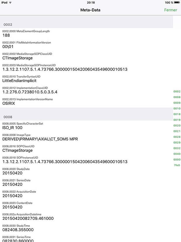
Today UTF-8 characters are supported in most DICOM applications, if they are configured correctly. The Specific Character Set (0008,0005) identifies the Character Set that expands or replaces the Basic Graphic Set for values of Data Elements that have Value Representation of SH, LO, ST, PN, LT or UT.  The defined term for multi-byte character sets without code extensions is ISO_IR 192.

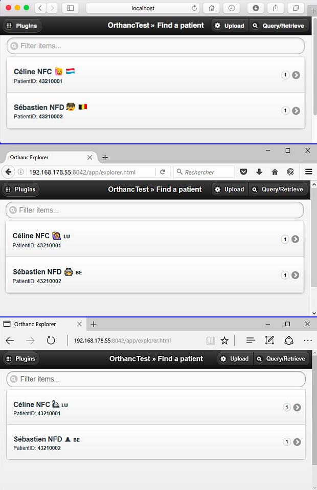
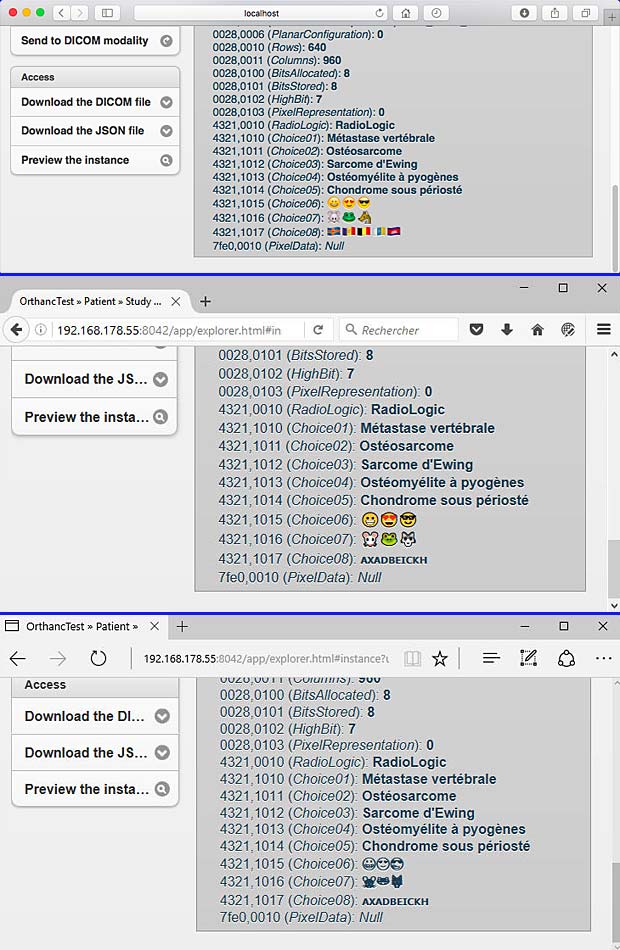
The next figure shows the use of UTF-8 characters in the Orthanc DICOM server.

Orthanc Explorer in 3 Web-Browsers : Safari, Firefox and Microsoft Edge

Orthanc Explorer “Patient Page” in different Web-Browsers : Safari, Firefox and Microsoft Edge

Orthac Explorer "Instance Page in different Web-Browsers : Safari, Firefox and Microsoft Edge

Orthanc Explorer “Instance Page” in different Web-Browsers : Safari, Firefox and Microsoft Edge

Links

Some links to websites providing additional informations about character encoding are listed hereafter :

OrthancMac OS X El Capitan

Last update : February 28, 2018

Introduction

I started the edition of this contribution in June 2015 when I did my first trials with the Orthanc server. In the meantime I created OrthancPi, a mini headless PACS server which is used to host the DICOM teaching files for RadioLogic, an educational tool for radiologists which is currently in alpha test state. It’s now time to update and finalize my post about the installation of the Orthanc server on my MacBookAir computer. The goal is the development of OrthancMac, a midi PACS server for RadioLogic which is more powerful and user-friendly than OrthancPi. Some figures included in the present post refer to earlier versions of Orthanc and to OS X Yosemite because it would be waste time to replace them all with current screenshots.

Some informations provided in the present post are trivial and redundant with my other posts about DICOM and Orthanc. I assembled them for my own needs to get familiar with Orthanc and OS X developments.

Orthanc

Orthanc is a open-source, lightweight DICOM server for healthcare and medical research. It’s now also called a VNA (Vendor Neutral Archive). Orthanc can turn any computer running Windows, Linux or OS X into a PACS  (picture archiving and communication system) system. Orthanc provides a RESTful API and is built on the top of DCMTK (collection of libraries and applications implementing large parts of the DICOM standard). Orthanc is standalone because all the dependencies can be statically linked.

The developer of Orthanc is Sébastian Jodogne, a belgian medical imaging engineer (2011) of the CHU of Liège (University Hospital) who holds a PhD in computer science (2006) from the University of Liège (ULG).

Orthanc source code

The Orthanc source code is available at Bitbucket. The latest stable Orthanc version is 1.3.1 released on November 2, 2017. Some changes have been done since that date. I downloaded the default (mainline) zip file from the Bitbucket project page and saved the unzipped orthanc folder into a directory named orthancmac located at the Mac OSX (El Capitan) desktop. My configuration is slightly different than the assumed structure in the Darwin compilation instructions, but I prefer this development setup.

The following folders and files are included in the orthanc folder :

  • Core/
  • OrthancExplorer/
  • OrthancServer
  • Plugins/
  • Resources/
  • UnitTestSources/
  • .travis.yml  (to trigger automated builds)
  • CMakeLists.txt
  • README, AUTHORS, COPYING, INSTALL, NEWS, THANKS
  • LinuxCompilation.txt and DarwinCompilation.txt

The build infrastructure of Orthanc is based upon CMake. The build scripts are designed to embed all the third-party dependencies directly inside the Orthanc executable. Cmake uses the concept Out of source Build where the build directory is separated from the source directory.

I created a folder build inside the orthanc directory and opened a terminal window inside this build folder.

cd desktop/orthancmac/orthanc/build

To prepare the build process (configuration) on Mac OS X El Capitan, I entered the following command in the terminal window :

cmake .. -GXcode -DCMAKE_OSX_DEPLOYMENT_TARGET=10.11
-DSTATIC_BUILD=ON -DSTANDALONE_BUILD=ON -DALLOW_DOWNLOAD=ON
~/desktop/orthancmac/build

The cmake options are :

-G : specify a makefile generator
-D : create a cmake cache entry

The cmake cache entries are :

CMAKE_OSX_DEPLOYMENT_TARGET : 10.11
STATIC_BUILD : ON
STANDALONE_BUILD : ON
ALLOW_DOWNLOAD : ON

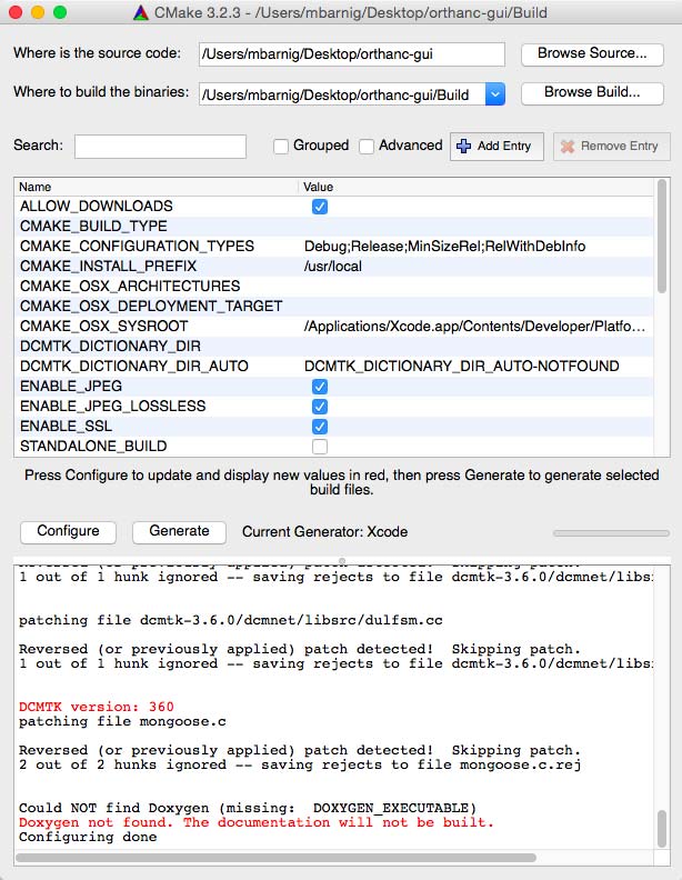
The following figure shows the configuration process when using the CMake-GUI :

Orthanc

Orthanc configuration with CMake GUI

During the configuration process, the following files have been downloaded from the website http://www.montefiore.ulg.ac.be/~jodogne/Orthanc/ThirdPartyDownloads/ :

All the files have been saved in a new folder orthancmac/orthanc/ThirdPartyDownloads. The programs SQlite3 and Python 2.7.10 have been found installed.

Configuration messages, warnings and errors

During the configuration process, the following messages, warnings and errors have been stated :

Files not found

The following files and definitions have not been found during the processing of DCMTK : fstream, malloc, ieeefp, iomanip, iostream, io, png, ndir, new, sstream, stat, strstream, strstrea, sync, sys/ndir, sys/utime, thread, unix, cuserid, _doprnt, itoa, sysinfo, _findfirst, isinf, isnan, uchar, ulong, longlong, ulonglong

Patching

The following files have been patched :

  • dcmtk-3.6.0/dcmnet/libsrc/dulfsm.cc
  • dcmtk-3.6.0/dcmnet/libsrc/dul.cc

Cmake policies

– policy CMP0042 not set
– policy CMP0054 not set
To avoid the cmake_policy warning, I added the following command to the  CmakeLists.txt file at the beginning :

if(POLICY CMP0042)
cmake_policy(SET CMP0042 NEW)
endif()
if(POLICY CMP0054)
cmake_policy(SET CMP0054 NEW)
endif()

INFOS

DCMTK’s builtin private dictionary support will be disabled
Thread support will be disabled
OS X Path not specified for the following targets:
– ModalityWorklists
– ServeFolders

DOXYGEN

Doxygen not found. The documentation will not be built.

Orthanc Xcode Building

The Build directory contains the following folders and files after the configuration and generation process :

  • AUTOGENERATED/
  • boost_1_60_0/
  • curl-7.50.3/
  • dcmtk-3.6.0/
  • gtest-1.7.0/
  • jpeg-9a/
  • jsoncpp-0.10.5/
  • libpng-1.5.12/
  • lua-5.1.5/
  • mongoose/
  • openssl-1.0.2d/
  • pugixml-1.4/
  • zlib-1.2.7/
  • CMakeFiles/
  • CMakeTmp/
  • CMakeScripts/
  • CMakeCache.txt
  • cmake_install.cmake
  • cmake_uninstall.cmake
  • Orthanc.xcodeproj

To build the project, I entered the following command in the terminal window inside the build folder :

xcodebuild -configuration Release

The build was successful, the following warnings have been issued :

  • 3 -> curl
  • 1 -> lua
  • 4 -> monggose
  • 5 -> zlib
  • 3 -> openssl
  • > 100 -> DCMTK
  • 1 -> Orthanc

The following figure shows the building process when using the Xcode GUI.

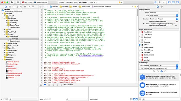
Orthanc

Orthanc Building with Xcode GUI

The eight targets are show at the left in red. To build the Release version, I modified the scheme in the Xcode-GUI. Building with the command line is much easier.

After the succesfull  build, the following folders and files were added to the Build folder :

  • Release/
  • Orthanc.build/

The Release folder contains the executables Orthanc, UnitTest and OrthancRecoverCompression, the libraries libCoreLibrary.a, libOpenSSL.a, libServerLibrary.a, libServeFolders.mainline.dylib and libModalityWorklists.mainline.dylib. These files are the targets of the Xcode building process.

Running the Orthanc server

The Orthanc configuration file Configuration.json is located in the folder orthanc-default/Resources. I copied this file into the Release folder and started the DICOM server with the command

./Orthanc Configuration.json

inside the Release folder.

Orthanc

Orthanc Server Start with Terminal Window

At the first start of the server, a new folder OrthancStorage is created inside the Release directory. The OrthancStorage folder contains the SQLite files index, index-shm and index-wal.

Entering the url localhost:8024 in the Safari address field opens the main window (explorer) of the Orthanc server.

Orthanc Explorer

Orthanc Explorer at localhost

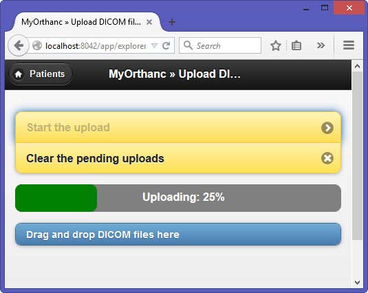
Clicking the upload button opens an new window in the Orthanc server where I added some DICOM files from CD’s (drag and drop).

Orthanc

Uploading DICOM files with Orthanc Server

The DICOM files are saved in sub-folders in the OrthancStorage directory in a flat structure.

I modified the configuration.json file to allow the remote access to the server from another computer located in the same local network.

/**
* Security-related options for the HTTP server
**/
// Whether remote hosts can connect to the HTTP server
"RemoteAccessAllowed" : true,

The remote anonymous access is now possible. When the remote access is not allowed, the server requests a user-id and password when entering the URL in the browser address bar :

http://192.168.168.55:8042/app/explorer.html

Orthanc allows the following actions :

Action Patient Study Series Instance
protect/unprotect x
delete x x x x
send to remote modality x x x x
anonimize x x x
preview x x
download ZIP x x x
download DICOMDIR x x x
download DICOM file x
download JSON file x

Protection

Because of its focus on low-end computers, Orthanc implements disk space recycling: the oldest series of images can be automatically deleted when the available disk space drops below a threshold, or when the number of stored series grows above a threshold. This enables the automated control of the disk space. Recycling is controlled by the MaximumStorageSize and the MaximumPatientCount options in the Orthanc configuration file. It is possible to prevent patient data from being automatically recycled by using the Unprotected/Protected switch that is available in Orthanc Explorer.

Testing the server

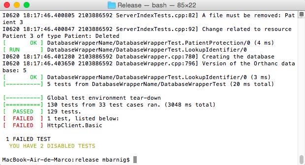
When the UnitTests executable is launched from the terminal window in the Release folder, 163 tests from 43 test cases were run. All these 163  tests passed. Two tests were disabled.

Orthanc UnitTests

Orthanc UnitTests

Two new folders were created in the Release folder by the testing process : UnitTestsResults and UnitTestsStorage.

RESTful API

The following list shows the main RESTful commands (links work only in my local network):

  • Patients : http://localhost:8042/patients
  • Studies : http://localhost:8042/studies
  • Series : http://localhost:8042/series
  • Instances : http://localhost:8042/instances
  • Patient Name : http://localhost:8042/patients/ba1682fb-3fc01dc1-acaf1294-c0d61888-69ba054b
  • Study CT Colonne cervicale : http://localhost:8042/studies/d4c42ef2-91794610-dfda2fe3-89fff37f-6d38b159
  • Series Col. Cervicale Mou 2.0 MPR spine multi : http://localhost:8042/series/e7f7f651-aeacf5d4-a3832d08-3c7a3efa-2eff3c3a
  • Instance 4 : http://localhost:8042/instances/8d5edbe5-073a70b9-c46dcaa7-9d54a495-6dc5ed32
  • Download instance.dcm : http://localhost:8042/instances/8d5edbe5-073a70b9-c46dcaa7-9d54a495-6dc5ed32/file
  • Simplified tags : http://localhost:8042/instances/8d5edbe5-073a70b9-c46dcaa7-9d54a495-6dc5ed32/simplified-tags
  • Tags : http://localhost:8042/instances/8d5edbe5-073a70b9-c46dcaa7-9d54a495-6dc5ed32/tags
  • Content : http://localhost:8042/instances/8d5edbe5-073a70b9-c46dcaa7-9d54a495-6dc5ed32/content
  • Preview : http://localhost:8042/instances/8d5edbe5-073a70b9-c46dcaa7-9d54a495-6dc5ed32/preview

A complete grid of the Orthanc RESTful API is available as Google Spreadsheet.

Links

Orthanc Book

Google groups discussions :

Other contributions :

Optional Variables in Apple Swift

Last update: October 26, 2016

Swift is Apples new programming language for iOS, OS X, watchOS, and tvOS app development. The current version is 3.0. Swift provides its own versions of all fundamental data types :

  • Int for integers
  • Double for 32 bit decimals (floating-point values)
  • Float for 64 bit decimals (floating-point values)
  • Bool for Boolean values
  • String for text

Integers are either signed (positive, zero, or negative) or unsigned (positive or zero). Integer literals can be written as:

  • A decimal number, with no prefix
  • A binary number, with a 0b prefix
  • An octal number, with a 0o prefix
  • A hexadecimal number, with a 0x prefix

Floating-point literals can be decimal (with no prefix), or hexadecimal (with a 0x prefix). Decimal floats can also have an optional exponent, indicated by an uppercase or lowercase e.

Swift also provides powerful versions of the three primary collection types :

  • Array
  • Set
  • Dictionary

Swift differentiates between constants and variables. The value of a constant cannot be changed once it is set, whereas a variable can be set to a different value in the future. Constant and variable names can contain almost any character, including Unicode characters.

let π = 3.14159
你好 = "你好世界"
🐶🐮 = "blablabla"

Constants are declared with the keyword “let”.

let myName = "Marco"

Constants are also called immutable because they cannot be changed after you have stored data in them.

Variables are declared with the keyword “var”. Variables are called mutable because you can constantly change the data that they store.

var x = 1.2

There are several possibilities to define a variable or a constant :

implicit :

var yourName = "Oscar"

explicit :

var yourName: String = "Oscar"

separated :

var yourName: String
yourName = "Oscar"

multiple line :

var x=1.2, y=3.4, z=5.6

typealias :

typealias FirstName = String
var hisName: FirstName = "Jeannot"

computed (getter) :

var number: Double {
  get {
    return x + y + z
    }
}

Swift is a type-safe language, which means the language prevents you from passing by mistake a wrong data type to a variable. Data Types can be converted with the functions Int( ), Double( ), Float( ), …

When a variable is declared, it can’t be used until data is stored in it, otherwise the program fails. Initially storing dummy data in a variable can cause errors. Therefore Swift uses the concept of optional variables. If an optional variable contains nothing, it’s considered to hold a value called nil. To create an optional variable, you declare it with its datatype, followed by a question mark :

var ourName : String?

Storing data in an optional variable is not different than storing data in an ordinary variable.

ourName = "Simone"

Retrieving data from an optional variable is however different and requires additional steps. After checking that the optional variable contains data, you have to unwrap it to get the actual data.  Unwrapping is done with the exclamation mark :

print(ourName!)

If you retrieve an optional variable containing a nil value the program will fail. Therefore we must first check that it contains data. This can be done in two ways :

explicit check

if ourName != nil {
   // retrieve value with ourName!
} else {
   // do something else
}

optional binding (constant assignment)

if let rumpelstilzchen = ourName {
  // retrieve value with rumpelstilzchen or ourName!
}

Optional variables are at the heart of many of Swift’s most powerful features. Once you understand the concept, they are very useful to link a user interface item to Swift code with IBOutlet variables.

A common user interface are text fields that are often empty at the program start. If a IBOutlet is defined as optional variable as follows

@IBOutlet weak var labelText: NSTextField?

we need to use the exclamation mark every time we want to access the data stored in this variable, which can be error prone and make the code hard to read. If we define the IBOutlet variable as an implicit unwrapped optional variable with an exclamation mark

@IBOutlet weak var labelText: NSTextField!

we can access it without question mark if it contains a value. In the case of IBOutlets Xcode catches any potential error, but this is not the case for other potential variables where you need to check and unwrap yourself the data.

The Aerial Bold Project

Aerial Bold : Kickstart the Planetary Search for Letterforms!” is the 11th Kickstarter project that I funded. The project was launched by Benedikt Groß & Joey Lee on October 14, 2014. After two weeks, 100% was funded by 480 bakers. At the end 569 backers pledged 11.492 $ to help bring this project to life.

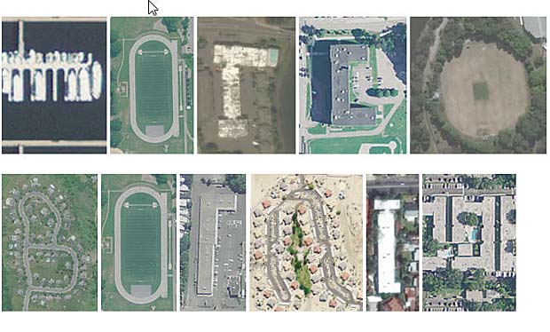
Aerial Bold is the first map and typeface of the earth. The project is literally about reading the earth for letterforms, or alphabet shapes, written into the topology of buildings, roads, rivers, trees, and lakes. To do this, Benedikt Groß and Joey Lee traversed the entire planet’s worth of satellite imagery and developed the tools and methods necessary to map these features hiding in plain sight.

On March 8, 2016, the results were finally presented. The entire letterform database has been made available as a usable dataset for any art – design – science – textual project. Selected letterforms have been converted into a truetype – opentype font format that can be imported into any word processor.

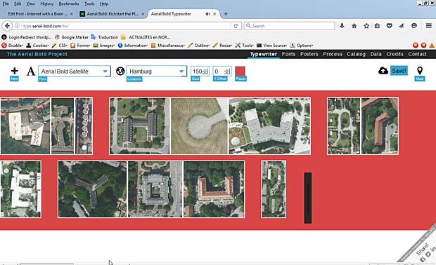
The results of the project are presented at the Aerial Bold Project website. An embedded typewriter allows to enter text with the different fonts :  Satellite, Buildings, Suburbia, Provence. The size, offset, background and location of the fonts can be selected.

Aerial Bold

Aerial Bold Typewriter : Satellite font, Hamburg, size 150, offset 0, red background

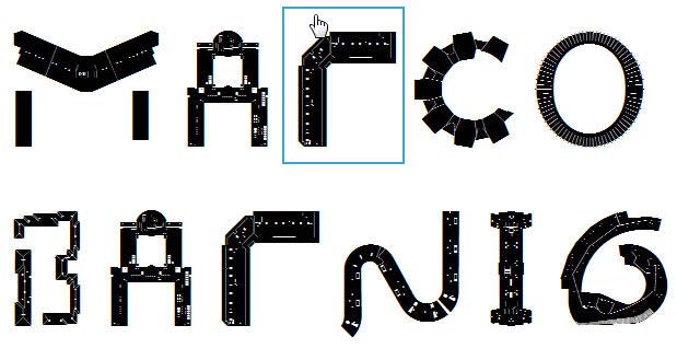
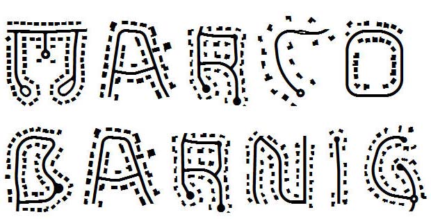
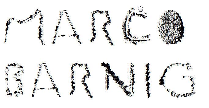
Additional information about the process, data, fonts and credits are available at the project website. A catalog and posters complete the documentation. Below are some pictures of my name written with the Aerial Bold fonts.

Aerial Bold Satellite Font

Aerial Bold Satellite Font

Aerial Bold Buildings Font

Aerial Bold Buildings Font

Aerial Bold Suburbia Font

Aerial Bold Suburbia Font

Aerial Bold Provence Font

Aerial Bold Provence Font

Orthanc Raspberry Pi

Last update : March 20, 2016

This contribution explains how to implement an Orthanc DICOM PACS Server on a Raspberry Pi (RPI) standalone single-board computer. The Orthanc source code was compiled on a Raspberry Pi 1 model B computer and tested on RPI models B Pi 1, Pi 2 and Pi 3. I use Raspbian Jessie for my RPI’s, a free operating system based on Debian, optimized for the Raspberry Pi hardware. I call the resulting mini PACS server an OrthancPi.

rpi

Raspberry Pi genealogy

Debian Med

An Orthanc package for Debian is available at the Debian website. This package is part of Debian Med, a specific flavour of Debian that is particularly well fit for the requirements for medical practice and biomedical research. The Debian Med package is maintained by the developer of Orthanc, Sébastien Jodogne, a Medical Imaging Engineer at the Medical Physics Department from the University Hospital of Liège (CHU) in Belgium.

The stable Orthanc version for Debian Jessie is 0.8.4. The Orthanc version 1.0 is only available for the testing (Stretch) and for the unstable (SID) Debian distributions. A release for the armhf architecture is part of the Orthanc package. The file list of the orthanc package in the Debian stretch distribution for the armhf architecture is the following :

/etc/init.d/orthanc
/etc/orthanc/orthanc.json
/etc/orthanc/serve-folders.json
/etc/orthanc/worklists.json
/usr/lib/orthanc/libModalityWorklists.so.1.0.0
/usr/lib/orthanc/libServeFolders.so.1.0.0
/usr/sbin/Orthanc
/usr/share/doc/orthanc/NEWS.gz
/usr/share/doc/orthanc/README.Debian
/usr/share/doc/orthanc/changelog.Debian.armhf.gz
/usr/share/doc/orthanc/changelog.Debian.gz
/usr/share/doc/orthanc/changelog.gz
/usr/share/doc/orthanc/copyright
/usr/share/lintian/overrides/orthanc
/usr/share/man/man1/Orthanc.1.gz
/usr/share/orthanc/plugins/libModalityWorklists.so
/usr/share/orthanc/plugins/libServeFolders.so

Orthanc Source Code

RPI’s are based on the ARM architecture and Raspbian releases usually follow the corresponding Debian release, but do deviate in a handful of cases. For this reason I preferred to build Orthanc version 1.0 from the source code, located on Bitbucket, on the Raspberry Pi hardware.

I downloaded the repository and put the content into a folder named Orthanc in the Raspberry Pi /home/pi/ directory. The following packages needed for compilation and linking have been installed first :

sudo apt-get install build-essential unzip cmake mercurial \
uuid-dev libcurl4-openssl-dev liblua5.1-0-dev \
libgoogle-glog-dev libgtest-dev libpng-dev libjpeg-dev \
libsqlite3-dev libssl-dev zlib1g-dev libdcmtk2-dev \
libboost-all-dev libwrap0-dev libjsoncpp-dev libpugixml-dev

I created a new folder OrthancBuild inside the /home/pi/ directory and executed the following commands :

cd OrthancBuild
cmake -DSTATIC_BUILD=ON -DCMAKE_BUILD_TYPE=Release ~/Orthanc
make

During the configuration process, the following files have been downloaded from the website http://www.montefiore.ulg.ac.be/~jodogne/Orthanc/ThirdPartyDownloads/ :

All the files have been saved in a new folder orthanc-default/ThirdPartyDownloads. All the third-party dependencies are statically linked to the Orthanc build. The compilation takes more time (several hours), compared to the default behavior where system wide libraries are used. Statically linked builds are however easier to share and to clone.

The result of the compilation was the generation of the following files :

  • Orthanc (executable)
  • UnitTests (executable)
  • libServeFolders.so.mainline (shared library) -> renamed to libServeFolders.so
  • libModalityWorklist.so.mainline (shared library) -> renamed to libModalityWorklist.so
  • libCoreLibrary.a (AR archive)
  • libServerLibrary.a (AR archive)
  • libOpenSSL.a (AR archive)

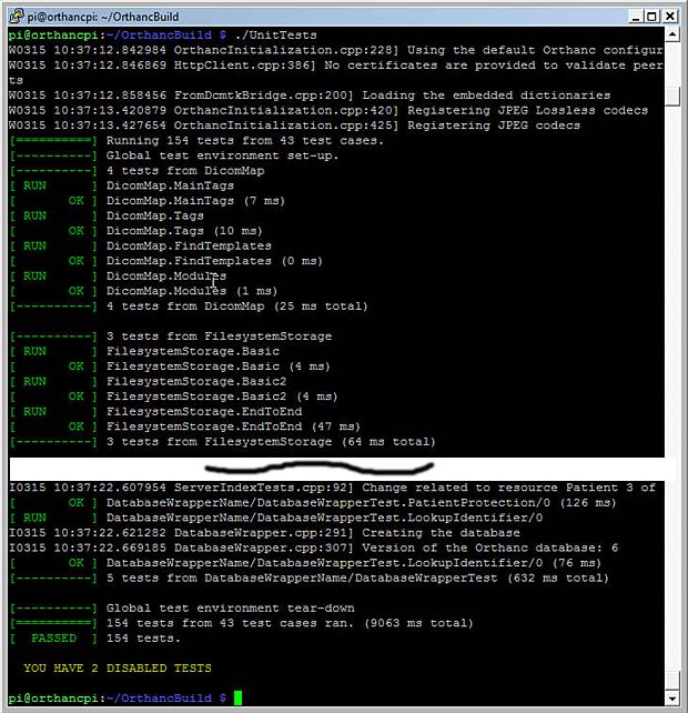
Running the UnitTests shows that all 154 tests from 43 test cases passed, 2 tests were disabled.

Orthanc UnitTests

Orthanc UnitTests

Orthanc plugins

I used the same procedure to compile the plugins DICOMweb and WebViewer. The source code was copied into the folders /home/pi/Dicomweb/ and /home/pi/Webviewer/. I created the new folders /home/pi/DicomwebBuild/ and /home/pi/WebviewerBuild and finally executed the commands

cd /home/pi/DicomwebBuild
cmake -DSTATIC_BUILD=ON -DCMAKE_BUILD_TYPE=Release ~/Dicomweb
make

cd /home/pi/WebviewerBuild
cmake -DSTATIC_BUILD=ON -DCMAKE_BUILD_TYPE=Release ~/Webviewer
make

The following third-party libraries are used by the plugins :

Dicomweb Webviewer
boost_1_59_0 boost_1_59_0
GDCM-prefix GDCM-prefix
gtest-1.7.0 gtest-1.7.0
jsoncpp-0.10.5 jsoncpp-0.10.5
pugixml-1.4
zlib-1.2.7
cornerstone-0.8.4
javascript-libs
jquery-ui-1.11.3
jspanel
jsurl-1.8.6
pako-0.2.5
sqlite-amalgamation-3071300

The shared libraries libOrthancDicomWeb.so.mainline and libOrthancWebViewer.so.mainline were created as a result of the compilation and linking process. I renamed these libraries without the mainline suffix.

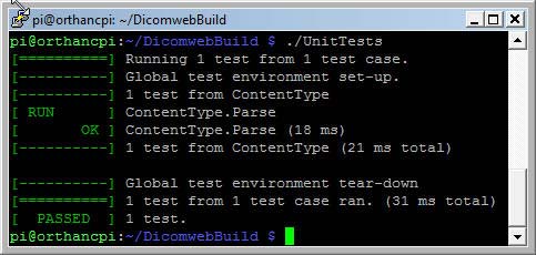
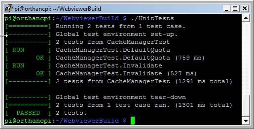
The results of the UnitTests runs are shown hereafter :

Orthanc DicomWeb UnitTests

Orthanc DicomWeb UnitTests

webviewer_tests

Orthanc WebViewer UnitTests

OrthancPi

The OrthancPi distribution files are assembled as follows in a directory named /home/pi/orthancpi/.

  • Orthanc  (executable)
  • UnitTests (executable)
  • configuration.json
  • /plugins/libServeFolders.so
  • /plugins/libModalityWorklists.so
  • /plugins/libOrthancDicomWeb.so
  • /plugins/libOrthancWebViewer.so.
  • /web/index.html (OrthancPi welcome page)
  • /python/ (empty)
  • /lua/ (empty)
  • /WorklistsDatabase/ (worklist samples)
  • /OrthancStorage/ (empty)

The default configuration.json file is created with the command

cd orthancpi
./Orthanc --config=configuration.json

I modified the configuration file as follows :

{
 // ***
 // General configuration of Orthanc
 // ***

 // The logical name of this instance of Orthanc. This one is
 // displayed in Orthanc Explorer and at the URI "/system".
  "Name" : "OrthancPi",

 // Path to the directory that holds the heavyweight files
 // (i.e. the raw DICOM instances)
  "StorageDirectory" : "OrthancStorage",

 // Path to the directory that holds the SQLite index (if unset,
 // the value of StorageDirectory is used). This index could be
 // stored on a RAM-drive or a SSD device for performance reasons.
  "IndexDirectory" : "OrthancStorage",

 // Enable the transparent compression of the DICOM instances
  "StorageCompression" : false,

 // Maximum size of the storage in MB (a value of "0" indicates no
 // limit on the storage size)
  "MaximumStorageSize" : 0,

 // Maximum number of patients that can be stored at a given time
 // in the storage (a value of "0" indicates no limit on the number
 // of patients)
  "MaximumPatientCount" : 0,
  
 // List of paths to the custom Lua scripts that are to be loaded
 // into this instance of Orthanc
  "LuaScripts" : [
  ],

 // List of paths to the plugins that are to be loaded into this
 // instance of Orthanc (e.g. "./libPluginTest.so" for Linux, or
 // "./PluginTest.dll" for Windows). These paths can refer to
 // folders, in which case they will be scanned non-recursively to
 // find shared libraries.
 
  "Plugins" : [
  "../plugins/libServeFolders.so",
  "../plugins/libOrthancWebViewer.so",
  "../plugins/libOrthancDicomWeb.so",
  "../plugins/libModalityWorklists.so"
  ],
  
"Worklists" : {
    "Enable": true,
    "Database": "../WorklistsDatabase"
  }, 
  
 "ServeFolders" : {
        "/web" : "/home/pi/orthancpi/web"
  },

  "DicomWeb" : {
     "Enable" : true,
     "Root" : "/dicom-web/",
     "EnableWadoo" : true,
     "WadooRoot" : "/wado",
     "Host" : "localhost",
     "Ss1" : false
  },

 // **
 //  Configuration of the HTTP server
 // **

 // Enable the HTTP server. If this parameter is set to "false",
 // Orthanc acts as a pure DICOM server. The REST API and Orthanc
 // Explorer will not be available.
  "HttpServerEnabled" : true,

 // HTTP port for the REST services and for the GUI
  "HttpPort" : 8042,

 // When the following option is "true", if an error is encountered
 // while calling the REST API, a JSON message describing the error
 // is put in the HTTP answer. This feature can be disabled if the
 // HTTP client does not properly handles such answers.
  "HttpDescribeErrors" : true,

 // Enable HTTP compression to improve network bandwidth utilization,
 // at the expense of more computations on the server. Orthanc
 // supports the "gzip" and "deflate" HTTP encodings.
  "HttpCompressionEnabled" : true,

 // **
 // Configuration of the DICOM server
 // **

 // Enable the DICOM server. If this parameter is set to "false",
 // Orthanc acts as a pure REST server. It will not be possible to
 // receive files or to do query/retrieve through the DICOM protocol.
  "DicomServerEnabled" : true,

 // The DICOM Application Entity Title
  "DicomAet" : "ORTHANCPI",

 // Check whether the called AET corresponds during a DICOM request
  "DicomCheckCalledAet" : false,

 // The DICOM port
  "DicomPort" : 4242,

 // The default encoding that is assumed for DICOM files without
 // "SpecificCharacterSet" DICOM tag. The allowed values are "Ascii",
 // "Utf8", "Latin1", "Latin2", "Latin3", "Latin4", "Latin5",
 // "Cyrillic", "Windows1251", "Arabic", "Greek", "Hebrew", "Thai",
 // "Japanese", and "Chinese".
  "DefaultEncoding" : "Utf8",

 // The transfer syntaxes that are accepted by Orthanc C-Store SCP
  "DeflatedTransferSyntaxAccepted"     : true,
  "JpegTransferSyntaxAccepted"         : true,
  "Jpeg2000TransferSyntaxAccepted"     : true,
  "JpegLosslessTransferSyntaxAccepted" : true,
  "JpipTransferSyntaxAccepted"         : true,
  "Mpeg2TransferSyntaxAccepted"        : true,
  "RleTransferSyntaxAccepted"          : true,

 // Whether Orthanc accepts to act as C-Store SCP for unknown storage
 // SOP classes (aka. "promiscuous mode")
  "UnknownSopClassAccepted"            : false,

 // **
 // Security-related options for the HTTP server
 // **

 // Whether remote hosts can connect to the HTTP server
  "RemoteAccessAllowed" : true,

 // Whether or not SSL is enabled
  "SslEnabled" : false,

 // Path to the SSL certificate (meaningful only if SSL is enabled)
  "SslCertificate" : "certificate.pem",

 // Whether or not the password protection is enabled
  "AuthenticationEnabled" : false,

 // The list of the registered users. Because Orthanc uses HTTP
 // Basic Authentication, the passwords are stored as plain text.
  "RegisteredUsers" : {
 // "alice" : "alicePassword"
  },

 // **
 //  Network topology
 // **

 // The list of the known DICOM modalities
  "DicomModalities" : {
 // **
 //    * Uncommenting the following line would enable Orthanc to
 //    * connect to an instance of the "storescp" open-source DICOM
 //    * store (shipped in the DCMTK distribution) started by the
 //    * command line "storescp 2000".
 //   **
 // "sample" : [ "STORESCP", "localhost", 2000 ]
	"Horos" : [ "HOROS", "192.168.123.200", 104 ],
	"dcm4che" : [ "DCM4CHE", "192.168.123.201", 104 ]

// **
//    * A fourth parameter is available to enable patches for a
//     * specific PACS manufacturer. The allowed values are currently
//    * "Generic" (default value), "StoreScp" (storescp tool from
//    * DCMTK), "ClearCanvas", "MedInria", "Dcm4Chee", "SyngoVia",
//    * "AgfaImpax" (Agfa IMPAX), "EFilm2" (eFilm version 2), and
//     * "Vitrea". This parameter is case-sensitive.
//  **
// "clearcanvas" : [ "CLEARCANVAS", "192.168.1.1", 104, "ClearCanvas" ]
  },

 // The list of the known Orthanc peers
  "OrthancPeers" : {
 // **
//     * Each line gives the base URL of an Orthanc peer, possibly
//    * followed by the username/password pair (if the password
//    * protection is enabled on the peer).
//  **
// "peer"  : [ "http://localhost:8043/", "alice", "alicePassword" ]
// "peer2" : [ "http://localhost:8044/" ]
	"OrthancMac" : [ "http://192.168.123.210:8042/" ]
  },

// Parameters of the HTTP proxy to be used by Orthanc. If set to the
// empty string, no HTTP proxy is used. For instance:
//   "HttpProxy" : "192.168.0.1:3128"
//   "HttpProxy" : "proxyUser:proxyPassword@192.168.0.1:3128"
  "HttpProxy" : "",

// Set the timeout for HTTP requests issued by Orthanc (in seconds).
  "HttpTimeout" : 10,

// Enable the verification of the peers during HTTPS requests.
// Reference: http://curl.haxx.se/docs/sslcerts.html
  "HttpsVerifyPeers" : true,

// Path to the CA (certification authority) certificates to validate
// peers in HTTPS requests. From curl documentation ("--cacert"
// option): "Tells curl to use the specified certificate file to
// verify the peers. The file may contain multiple CA
// certificates. The certificate(s) must be in PEM format."
  "HttpsCACertificates" : "",

// **
// Advanced options
// **

// Dictionary of symbolic names for the user-defined metadata. Each
// entry must map an unique string to an unique number between 1024
// and 65535.
  "UserMetadata" : {
 // "Sample" : 1024
  },

// Dictionary of symbolic names for the user-defined types of
// attached files. Each entry must map an unique string to an unique
// number between 1024 and 65535. Optionally, a second argument can
// provided to specify a MIME content type for the attachment.
  "UserContentType" : {
 // "sample" : 1024
 // "sample2" : [ 1025, "application/pdf" ]
  },

// Number of seconds without receiving any instance before a
// patient, a study or a series is considered as stable.
  "StableAge" : 60,

// By default, Orthanc compares AET (Application Entity Titles) in a
// case-insensitive way. Setting this option to "true" will enable
// case-sensitive matching.
  "StrictAetComparison" : false,

// When the following option is "true", the MD5 of the DICOM files
// will be computed and stored in the Orthanc database. This
// information can be used to detect disk corruption, at the price
// of a small performance overhead.
  "StoreMD5ForAttachments" : true,

// The maximum number of results for a single C-FIND request at the
// Patient, Study or Series level. Setting this option to "0" means
// no limit.
  "LimitFindResults" : 0,

// The maximum number of results for a single C-FIND request at the
// Instance level. Setting this option to "0" means no limit.
  "LimitFindInstances" : 0,

// The maximum number of active jobs in the Orthanc scheduler. When
// this limit is reached, the addition of new jobs is blocked until
// some job finishes.
  "LimitJobs" : 10,

// If this option is set to "false", Orthanc will not log the
// resources that are exported to other DICOM modalities of Orthanc
// peers in the URI "/exports". This is useful to prevent the index
// to grow indefinitely in auto-routing tasks.
  "LogExportedResources" : true,

// Enable or disable HTTP Keep-Alive (deprecated). Set this option
// to "true" only in the case of high HTTP loads.
  "KeepAlive" : false,

// If this option is set to "false", Orthanc will run in index-only
// mode. The DICOM files will not be stored on the drive. Note that
// this option might prevent the upgrade to newer versions of Orthanc.
  "StoreDicom" : true,

// DICOM associations are kept open as long as new DICOM commands
// are issued. This option sets the number of seconds of inactivity
// to wait before automatically closing a DICOM association. If set
// to 0, the connection is closed immediately.
  "DicomAssociationCloseDelay" : 5,

  // Maximum number of query/retrieve DICOM requests that are
  // maintained by Orthanc. The least recently used requests get
  // deleted as new requests are issued.
  "QueryRetrieveSize" : 10,

// When handling a C-Find SCP request, setting this flag to "true"
// will enable case-sensitive match for PN value representation
// (such as PatientName). By default, the search is
// case-insensitive, which does not follow the DICOM standard.
  "CaseSensitivePN" : false,
  
// Register a new tag in the dictionary of DICOM tags that are known
// to Orthanc. Each line must contain the tag (formatted as 2
// hexadecimal numbers), the value representation (2 upcase
// characters), a nickname for the tag, possibly the minimum
// multiplicity (> 0 with defaults to 1), and possibly the maximum
// multiplicity (0 means arbitrary multiplicity, defaults to 1).
  "Dictionary" : {
// "0014,1020" : [ "DA", "ValidationExpiryDate", 1, 1 ]
  }
}

I copied the whole orthancpi directory with an USB card reader to different Raspberry Pi modules which were configured to run as headless servers with remote control, using various wifi adapters. The process is explained in my post Rasperry Pi revisited.

To start the OrthancPi server at boot, a file orthanc.desktop has been added to the /home/pi/.config/autostart/ folder. This is the content of this file

[Desktop Entry]
Type=Application
Name=ORTHANC
Exec=/home/pi/orthancpi/Orthanc /home/pi/orthancpi/configuration.json
StartupNotify=false

OrthancPi can also be configured to run as a Debian daemon.

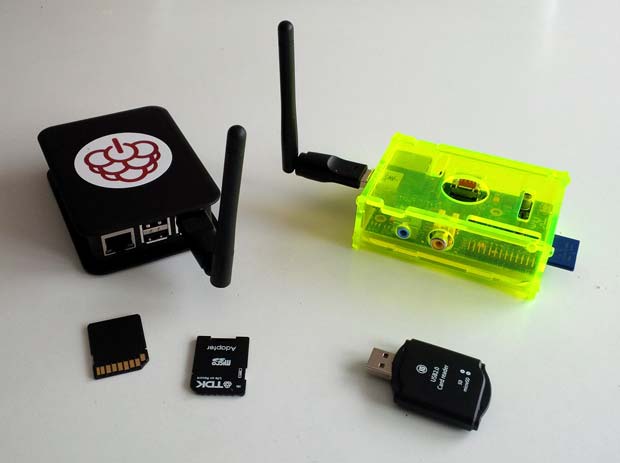
An OrthancPi server will be used in the context of the RadioLogic project, a training tool for radiology. This tool will be used in classrooms without Internet access. The OrthancPi server works as wireless access point. To extend the WiFi range, a  repeater can be used. The RadioLogic tool is web based and optimized to run on iPad’s which are connected to the OrthancPi WLAN. The following figure shows two OrthancPi servers with USB WiFi adapters using  Ralink RT5370 chips.

OrthancPi's with USB WiFi adapters, SDcards and SDcard-reader

OrthancPi’s with USB WiFi adapters, SDcards and SDcard-reader

A user guide for the OrthancPi is available at the RadioLogic website. Disk image files to set up an OrthancPi server in a plug and play way, with different WiFi adapters, are available at the same webpage.

Raspberry Pi Revisited

Last update : March 20, 2016

Referring to my first post about the Raspberry Pi, I am pleased to provide an update about my ongoing projects, with a special focus on a wireless headless operation. Headless means running it without a mouse, keyboard and monitor, via network connections. Wireless means using a WLAN connection with a WiFi dongle.
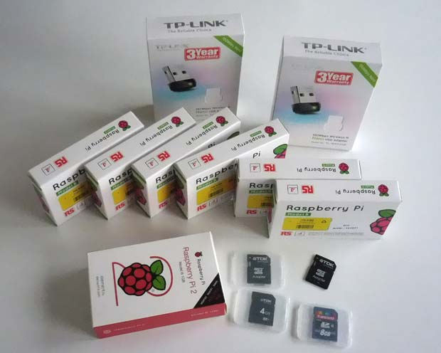
Raspberry Pi's

Raspberry Pi’s with SDcards and WiFi dongles

Raspbian Jessie

A new Raspbian (the Raspberry Pi Foundation’s official supported operating system) version, based on Debian Jessie, was launched on November 21, 2015. Updates were released on February 9, February 26 and March 18, 2016. I upgraded my Raspberry Pi computers to the February 26 version (kernel 4.1.18+ on RPi 1 models; kernel 4.1.18-v7+ on RPi 2 and 3 models). I used the same procedure as last time : writing the downloaded Raspbian image with the Win32DiskImager tool on my Windows computer to 8GB and 16GB SDcards. The current version of this tool is 0.9.5, released on March 19, 2014.
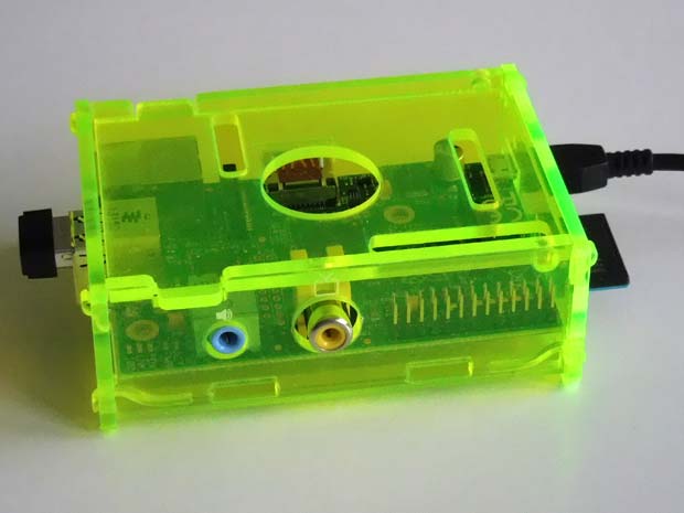
Raspberry Pi model B

Raspberry Pi model B

It was not possible to overwrite the old Raspbian image on my Raspberry Pi SDcards with the new one. Reformatting the used SDcards with the usual tools (diskpart, SDCard Formatter 4, …) was not successful. Windows sees only the 56 MB FAT32 partition, but not the much larger Linux partition. It was not possible to recover the lost space. After some trials and errors, I finally reformatted the SDcards in my Nikon camera. It worked like a charm. Writing the new Raspbian image to the new formatted SDcards was then no problem.
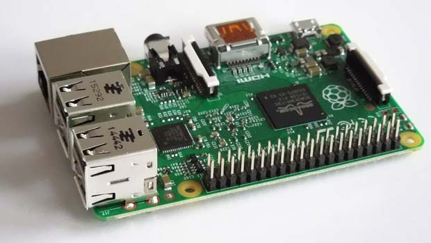
Raspberry Pi model 2

Raspberry Pi model 2

Configuring Raspbian

After the first booting of the Raspberry Pi computer, the new desktop appears.
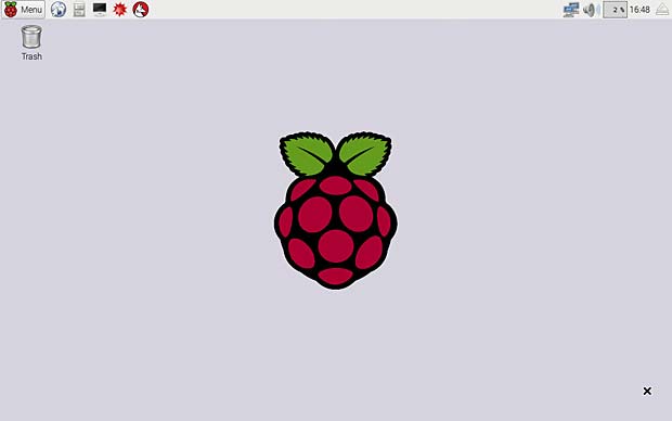
Raspian Jessie Desktop

Raspbian Jessie Desktop

The desktop contains only one icon : the Trash. The Raspberry logo is shown in the center. The menu is in the left upper corner, some icons are in the right upper corner. It’s possible to reconfigure the menu list. One new icon is the network configuration tool based on Roy Marples‘s dhcpcd and dhcpcd-ui packages.

The configuration panel allows to expand the filesystem.
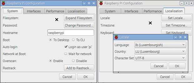
Raspberry Pi Configuration

Raspberry Pi Configuration

After expanding and rebooting the system, the File Manager (PCManFM 1.2.3) shows a free space of 3,6 GB on my 8GB SDcard, compared to a free space of 98,1 MB before the expansion. The Raspbian Jessie version allows to set the locale to “lb” for Luxembourg in the localisation tab, and Luxembourg is also included as country in the timezone list. The french-swiss keyboard used in Luxembourg figures now, as expected, among the Switzerland keyboards.

The computer was recognized by my Fritzbox router and the IP address 192.168.178.62 was assigned by the DHCP server.

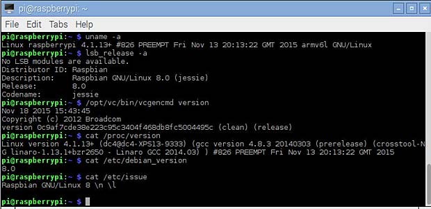
Updating and checking the Raspbian version

The file /etc/apt/sources.list contains the following source (one line) :

deb http://mirrordirector.raspian.org/raspian/ 
jessie main contrib non-free rpi

I replaced mirrordirector by archive to avoid numerous download fails. To download the source code of packages with apt-get source, the following line should be un-commented in the sources.list file (one line) :

deb-src http://archive.raspian.org/raspian/ 
jessie main contrib non-free rpi

Raspbian Jessie is based on Linux version 8. A lite version without the GUI is separately available. I preferred to install the full version and to remove some large packages like Wolfram, Office and some games with the following command :

sudo apt-get remove --purge wolfram-engine libreoffice* minecraft-pi \
python-minecraftpi python3-minecraftpi

The files /usr/share/raspi-ui-overrides/applications/wolfram-mathematica.desktop and ../wolfram-language.desktop must be deleted to remove the related empty icons in the task bar.

To install the additional packages needed for the headless operation I entered the command :

sudo apt-get update
sudo apt-get install x11vnc hostapd dnsmasq lighttpd haveged

Lists of the resulting installed packages for my project are provided at the following links :

The default Raspbian terminal application is LXTerminal.

To upgrade all Debian packages to the latest version, I launched the well known commands

sudo apt-get update
sudo apt-get upgrade

in the terminal window. Two packages were upgraded. To show the installed versions, we can use the following commands :

  • uname – a        > kernel
  • lsb_release -a       > distribution
  • /opt/vc/bin/vcgencmd version       > firmware
  • cat  /proc/version
  • cat  /proc/cpuinfo     > CPU
  • cat  /proc/meminfo    > memory
  • cat  /proc/partitions    > partitions
  • cat  /etc/debian_version
  • cat  /etc/issue
Show Raspian Versions

Show Raspban versions and system informations

The command dmesg (display message or driver message) prints the message buffer of the kernel. An error “bcm2708_fb soc.fb: Unknown ioctl 0x40187a22” is listed.

dmesg

display the Raspberry Pi kernel message buffer

Remote Control

There are several methods available to remotely control a headless Raspberry Pi computer. The most common are :

  • Secure Shell (SSH)
  • Remote Desktop (RDP)
  • Tight-VNC
  • X11-VNC

SSH

An SSH client is a software program which uses the secure shell protocol to connect to a remote computer. SSH provides a secure channel over an unsecured network in a client-server architecture. There are numerous SSH clients available for the different operating systems. For Windows an often used SSH program is PuTTY. PuTTY is a free and open-source terminal emulator, serial console and network file transfer application which was written and is maintained primarily by Simon Tatham.
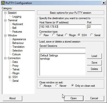
Putty

Secure Shell Terminal PuTTY for Windows

The following security alert is displayed by the PuTTY terminal at the first connection to a new server.
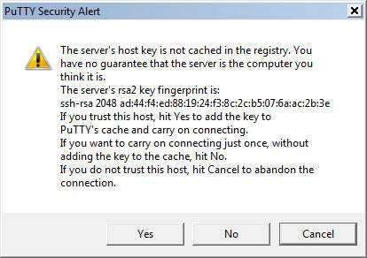
Alert

PuTTY security alert

The next figure shows the welcome message sent by the Raspberry Pi after a successful login. The default user name is pi and the default password is raspberry.These parameters can be changed in the Raspbian configuration.
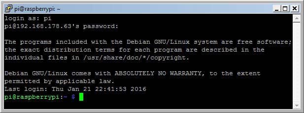
Putty

PuTTY welcome message

The Apple Mac computers have an integrated secure shell in the standard terminal program. A connection can be established with the following command :

ssh username@server
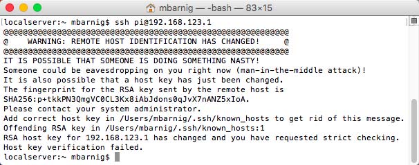
os

Secure shell in a MacBook Air

I use the WebSSH app for my iOS devices and the JuiceSSH app for my Android tablets.

RDP

Remote Desktop Protocol (RDP) is a proprietary protocol developed by Microsoft, which provides a user with a graphical interface to connect to another computer over a network connection. The user employs RDP-client software for this purpose, while the other computer must run RDP-server software.

To install the remote desktop server application XRDP (version 0.6.1-2) on Raspberry Pi, I launched the command

sudo apt-get install xrdp

The next figure shows the Remote Desktop Connection Panel on Windows :
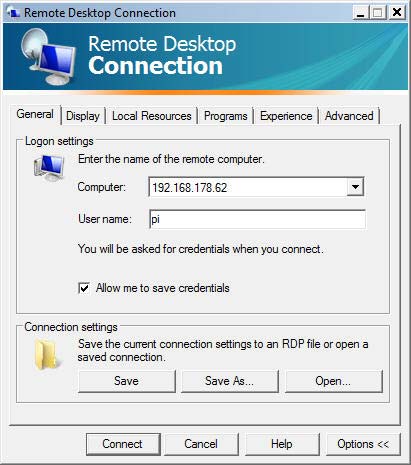
XRDP

XRDP Logon settings

RDP Clients exist not only for Windows and Windows Mobile, but also for OS X (version 8.0.24) , Linux, iOS (version 8.1.17) and Android.

The problem with european keyboards explained in my former Raspberry Pi contribution persist and is even more difficult to solve on tablets. For this reason I discarded the RDP solution for my future projects.

Tight-VNC

Tight-VNC is a cross-platform free and open-source remote desktop software application that uses and extends the remote framebuffer (RFB) protocol of Virtual Network Computing (VNC) to control another computer’s screen remotely. It was created by Constantin Kaplinsky.

Most tutorials about remote desktops refer to the Tight-VNC-Server as favorite solution. One disadvantage of this application is that it uses only virtual desktops, which is not optimal for a headless operation of a computer. Therefore I discarded the Tight-VNC-Server for my projects, but i use the Tight-VNC-Client on Windows as viewer to work with an X11-VNC-Server.

X11-VNC

X11-VNC allows remote access from a remote client to a computer hosting an X Window (X11) session and the x11vnc server software, continuously polling the X server’s frame buffer for changes. X11-VNC does not create an extra display for remote control. Instead, it uses the existing X11-display shown on the monitor in real time.

To install an X11-VNC-server on Raspberry Pi, we enter the command

sudo apt-get install x11vnc

To start the server the first time we use the command

x11vnc -usepw -forever -display :0

A password (= raspberry) is defined at this first launch, verified and saved in the /home/pi/.vnc/ directory. The window 0 refers to the visible desktop and is related to the port number 5900. Additional virtual desktops can be configured with the display numbers 1, 2, 3 … and are associated with the port numbers 5901, 5902, 5903 … To launch the VNC-server automatically when the Raspberry Pi boots, we create an auto-start file

/home/pi/.config/autostart/x11vnc.desktop

with the following content :

[Desktop Entry]
Type=Application
Name=X11VNC
Exec=x11vnc -usepw -forever -display :0
StartupNotify=false

A VNC viewer is installed at a remote computer to access the Raspberry Pi desktop. I use the free Tight-VNC-Viewer for Windows (version 2.7.10 released on July 24, 2013) and the RealVNC viewer for iOS (version 2.4.1 released on December 2, 2015). A VNC viewer is also available for Android (version 2.0.0.016450 released on February 11, 2016) and other operating systems. A VNC client is integrated in OS X an can be opened in Safari with the command

vnc://IP address:port number

The VNC-server takes the display size from the resolution of the connected HDMI monitor. In case of headless operation, the display size on the VNC viewer is very small. To adapt the display size to the iPad (my preferred VNC viewer), I uncommented and modified the following lines in the configuration file /boot/config.txt.

hdmi_force_hotplug=1
hdmi_group=2
hdmi_mode=16
hdmi_drive=2

For security reasons I configured the VNC-server to be only accessible in the local network.

WLAN Adapters

To set up a WiFi connection to access the Raspberry Pi wirelessly, we need a WiFi dongle. I use the following 150Mbps Wireless N Nano USB adapters for my Raspberry Pi projects :

The Raspberry Pi 3 model has an onboard WiFi chip. The command lsusb shows the ID of the dongles, here for the official Raspberry WiFi adapter.

lsusb

lsusb result for Raspberry dongle : Bus 001 Device 004 = Broadcom Corp. ID 0a5c:bd1e

The command lsmod shows which loadable kernel modules are currently loaded.
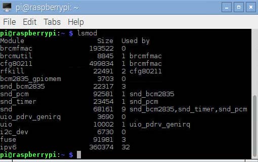
lsmod

lsmod result for the Raspberry WiFi dongle

The modules related to the Broadcom WiFi dongle are brcmfmac, brcmutil and cfg80211. Detailed informations about these modules are obtained with the command modinfo modulename :
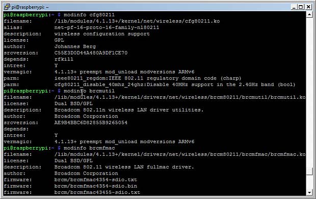
modinfo

modinfo results for the Raspberry WiFi dongle

The associated preinstalled drivers and utilities are

/lib/modules/4.1.18+/kernel/drivers/net/wireless/brcm80211/brcmfmac/brcmfmac.ko
/lib/modules/4.1.18+/kernel/drivers/net/wireless/brcm80211/brcmutil/brcmutil.ko
/lib/modules/4.1.18+/kernel/net/wireless/cfg80211.ko

In the case of a RPi 2 or 3 device, the module is /4.1.18-V7+/.

The command iw list shows the features of the installed WiFi dongle.
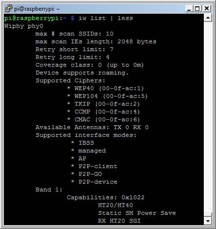
iw list results

iw list results for the Raspberry WiFi dongle

Among the listed features, the supported interface modes are the most important. The support of AP means that the WiFi dongle can be used as WLAN access point.

The command dmesg (display message or driver message) prints the message buffer of the kernel. The result shows an issue with the brcmfmac driver for the official Raspberry WiFi dongle.
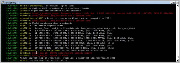
brcmfmac

brcmfmac errors issued by dmesg command

[ 11.060813] brcmfmac: brcmf_c_preinit_dcmds: 
Firmware version = wl0: Apr 3 2014 04:43:32 
version 6.10.198.66 (r467479) FWID 01-32bd010e
[ 11.105542] brcmfmac: brcmf_cfg80211_reg_notifier: not a ISO3166 code
[ 14.284071] brcmfmac: brcmf_add_if: ERROR: netdev:wlan0 already exists
[ 14.284233] brcmfmac: brcmf_add_if: ignore IF event

Nevertheless the official WiFi dongle seems to work as expected.

Running the commands lsusb, lsmod and iwlist for the other 3 WiFi dongles and the onboard WiFi chip allows me to dress the following table :
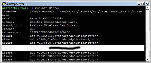
Dongle Chipset ID WPA driver AP support
D-Link DWA-131 Realtek RTL8192CU 2001:330d 8192cu.ko yes
TP-Link TL-WN725N Realtek RTL8188EUS 0bda:8179 8188eu.ko yes
Raspberry WiFi Broadcom BCM43143 0a5c:bd1e brcmfmac.ko yes
Racksoy Mini Stick Ralink RT5370 148f:5370 rt2800usb.ko yes
RPI 3 onboard chip Broadcom BCM43438 ————- brcmfmac.ko yes
8192cu

lsusb result for the Wifi dongle D-LINK DWA-131 (module 8192cu)

The command modinfo 8192cu confirms that the dongle with ID 2001:330d is supported by the preinstalled driver 8192.ko located at

/lib/modules/4.1.18+/kernel/drivers/net/wireless/rtl8192cu/8192cu.ko

The WiFi dongles Raspberry, Racksoy and D-Link DWA-131 work out of the box in my Raspberry Pi. The following figure shows the Raspian Desktop with the activated Wifi icon. The two pasted message panels show the informations displayed when the mouse hovers the WiFi icon : the first case with additional wired Ethernet connection, the second case without Ethernet connection.
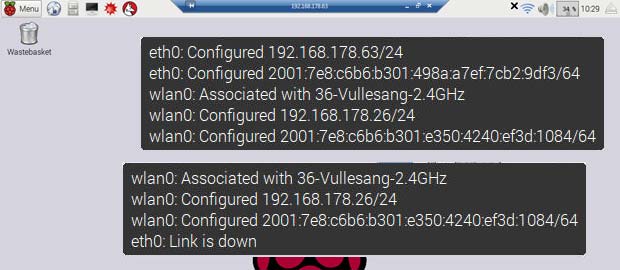
WiFi

Raspbian WiFi information panel

The next figure shows the information displayed in my Fritzbox gateway concerning the WLAN and the Ethernet connections of the Raspberry Pi :

WiFi

Raspberry Pi connections listed in the Fritzbox home-network panel

The fourth WiFi dongle (TP-Link TL-WN725N) uses the Realtek rtl8188EUS chip. Out of the box, the dongle worked, but with a very low signal indicator, although the Raspberry Pi was near my WLAN gateway. The lsmod command shows a driver r8188eu among the currently loaded kernel modules. This driver r8188eu.ko is located in the folder

/lib/modules/4.1.18+/kernel/drivers/staging/rtl8188eu/

The Linux Staging tree is used to hold stand-alone drivers and filesystems that are not ready to be merged into the main portion of the Linux kernel tree, at this point in time, for various technical reasons. The correct driver named 8188eu.ko is not included in the Raspbian Jessie version. TP-Link and Realtek provide source files to compile the driver for specific Linux distributions. An installation guide is included in the zip-compressed driver file. Precompiled drivers for the Raspberry Pi are provided by the community. I used such a precompiled driver for my Linux version 4.1.18+, available at the following link :

https://dl.dropboxusercontent.com/u/80256631/8188eu-20160219.tar.gz

The precompiled package with the 8188eu.ko driver contains a script install.sh to automatize the installation process. I preferred to do it manually. I installed the included driver 8188eu.ko into a new created folder rtl8188 inside the wireless driver directory with the commands

sudo install -p -m 644 8188eu.ko 
/lib/modules/4.1.18+/kernel/drivers/net/wireless/rtl818x/rtl8188
sudo depmod 4.1.18+

Finally I copied the included file 8188eu.conf, blacklisting the staging driver r8188 to the directory

/etc/modprobe.d/

modprobe is a Linux program used to add a loadable kernel module to the Linux kernel or to remove a module from the kernel.

After rebooting the dongle works as expected. For practical reasons I linked copies of the files 8188eu.ko and 8188eu.conf in the present post.

WPA_Supplicant

To connect the Raspberry to a remote WLAN Access Point, a software must run to provide WPA key negotiation with a WPA Authenticator and EAP authentication with an Authentication Server. The most common program for these tasks is wpa_supplicant, a free IEEE 802.11i software implementation developed by Jouni Malinen. In computer networking, a supplicant is an entity at one end of a point-to-point LAN segment that seeks to be authenticated by an authenticator attached to the other end of that link.

wpa_supplicant is a daemon and only one instance of it may run on a machine, all other modifications of security settings are made with the text-based frontend application wpa_cli. wpa_cli is used to query current status, change configuration, trigger events, and request interactive user input. wpa_supplicant is pre-installed in Raspbian Jessie.
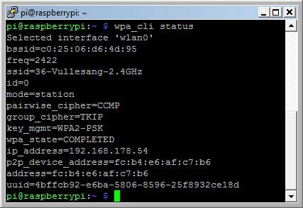
wpa_cli status

wpa_cli status

wpa_cli works two ways: interactive and non-interactive

A list of some useful wpa_cli commands is shown below :

  • wpa_cli status
  • wpa_cli terminate

The following command can be used to restart the WiFi connection :

sudo /etc/init.d/networking restart

The wpa configuration file located at /etc/wpa_supplicant/wpa_supplicant.conf has the following content :

ctrl_interface=DIR=/var/run/wpa_supplicant GROUP=netdev
update_config=1
network={
ssid="36-Vullesang-2.4GHz"
psk="secretkey"
key_mgmt=WPA-PSK
}

Hostapd

To use a WiFi dongle in AP mode on Rasperry, you need hostapd or a similar application. wpa_supplicant allows basic AP configuration, but does not include support for most of the AP parameters. Comparing the hostapd.conf with the wpa_supplicant.conf example provides a picture of the difference.

The hostapd module is not pre-installed in Raspbian Jessie. The installation is done as usually with the command

sudo apt-get install hostapd

The version check after the successful installation shows version number 2.3.

hostapd version

hostapd version check

hostapd is developed and maintained by the author of wpa_supplicant, Jouni Malinen from Finland.

I edited the related configuration file

/etc/hostapd/hostapd.conf

as follows for an open network :

# WLAN Router Configuration
interface=wlan0
# driver= autoselected
ssid=radiologic
ignore_broadcast_ssid=0
channel=6 
hw_mode=g 
wmm_enabled=1 
auth_algs=1

To protect and encrypt the network, the following parameters are added to the hostapd.conf file :

# WLAN Encryption 
wpa=2 
rsn_preauth=1 
rsn_preauth_interfaces=wlan0 
wpa_key_mgmt=WPA-PSK 
rsn_pairwise=CCMP 
wpa_passphrase=123456789

Here is a link to my hostapd.conf file. Some explanations about the different configuration parameters used are listed below :

  • # : lines starting with an hash are considered as comments
  • interface : name of the interface to listen on
  • driver : usually detected by the system; in case of failure the name of the driver corresponding to the used dongle must be specified (nl80211, rtl871xdrv, …)
  • ssid : name of the network seen by other devices
  • ignore_broadcast_ssid : define if the network name is visible (broadcasted) or hidden
  • channel : WiFi channel used by the network; valid channels range from 1 to 11 or from 1 to 14, depending on the location
  • hw_mode : wireless mode : A, B and G are available; these are the last characters of the IEEE 802.11 standard. The most common is G (2,4 GHz).
  • wmm_enabled : WiFi multimedia to enhance quality of service (QoS)
  • auth_algs : specification of the authentication algorithm; 1 = OSA
  • country_code : used to set regulatory domain (transmit power, available channels)
  • ieee80211d : set the regulatory limits based on the country code
  • ieee80211n : optional activation of the IEEE 802.11n standard
  • wpa : security settings: 1=wpa; 2=wpa2; 3=wpa & wpa2
  • rsn_preauth :pre-authentication to speed up roaming
  • rsn_preauth_interfaces : list of interfaces from which pre-authentication frames are accepted
  • wpa_key_mgmt : management of the wpa2 WLAN keys; WPA-PSK or WPA-EA
  • rsn_pairwise : encryption algorithm for wpa2; new CCMP or old TKIP
  • wpa_pairwise : encryption algorithm for wpa
  • wpa_passphrase : password specified for the network
  • logger-syslog : instructions about error logging
  • max_num_sta : maximal number of clients accepted by the WLAN
  • deny_mac_file : prevent connections from devices with a MAC address specified in a file

The complete list of hostapd parameters is available at the website of the developer.

The Raspberry WiFi dongle works out of the box with the default hostapd driver nl80211. The Racksoy WiFi dongle works with the autoselected driver rt2800.

Hostapd supporting driver rtl871xdrv

The two other WiFi dongles D-Link DWA-131 and TP-Link TL-WN725N are not supported by the standard hostapd module with the included drivers. Both dongles use Realtek chipsets needing a specific driver, named rtl871xdrv. There are numerous posts and tutorials available at the web dealing with this problem, but only few provide correct and relevant solutions related to the current Raspbian Jessie version.

After some Trial and Error, I ended up with the following procedure :

  1. download the version 2.5 of the hostapd source https://w1.fi/releases/hostapd-2.5.tar.gz from the website https://w1.fi/hostapd/ of Jouni Malinen
  2. extract the archive at /home/pi/hostapd-2.5/
  3. clone the github repository https://github.com/pritambaral/hostapd-rtl871xdrv at /home/pi/hostapd-rtl871xdrv/ with the command
    sudo git clone https://github.com/pritambaral/hostapd-rtl871xdrv
  4. install the modules libnl1, libnl-dev and libssl-dev with the command
    sudo apt-get install libnl1 libnl-dev libssl-dev
  5. change directory to /home/pi/hostapd-2.5/
  6. apply the patch code with the command
    sudo patch -Np1 -i /home/pi/hostapd-rtl871xdrv/rtlxdrv.patch
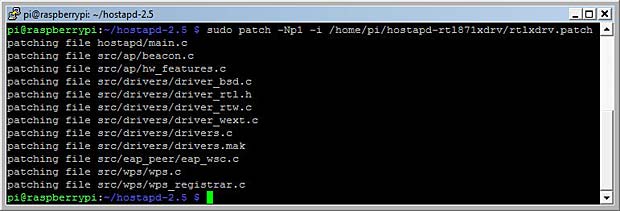
    Patching the hostapd source

    Patching the hostapd source files

  7. enable the driver in the file .config with the commands
    cd hostapd
    cp defconfig .config
    echo CONFIG_DRIVER_RTW=y >> .config
  8. compile the hostapd module, inside the hostapd folder, with the following command
    sudo make install
  9. check the new installed hostapd version
hostapd version 2.5

hostapd version 2.5 for Realtek rtl871xdrv

The last step is to change the driver name as rtl871xdrv in the hostapd.conf file and to reboot the Raspberry Pi with a Realtek WiFi dongle. After terminating wpa_cli and starting hostapd, we get the confirmation that the Realtek dongles are now working.
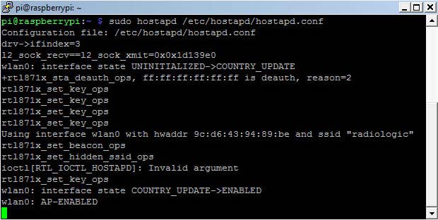
hostapd

hostapd launch with driver rtl871xdrv

Running Hostapd

Depending on the used WiFi dongle, we use the native hostapd version 2.3 or the new compiled version 2.5. Before associating hostapd with the wlan0 interface, we have to disassociate this interface with wpa_supplicant by entering the command

sudo wpa_cli terminate

To start the WLAN-Host, we run the command

sudo hostapd /etc/hostapd/hostapd.conf

Adding the optional parameter -dd (after hostapd) in the above command provides a detailed report about the process, which can be very helpful in case of problems. After a few moments the WiFi-panel in the Raspian desktop shows that the wlan0 interface is ssociated with the SSID “radiologic”. The interface is configured as AdHoc network with an self-assigned IP address in the range 169.254.0.0/16.

WiFi panel when hostapd is started

WiFi panel when hostapd is started

I used an iPad as WLAN client to test the WLAN-Host. The SSID “radiologic” is displayed in the list of available WiFi networks as secured WLAN. After entering the defined password “123456789”, the connection is established. The next figure shows the related messages displayed in the Raspbian terminal window.
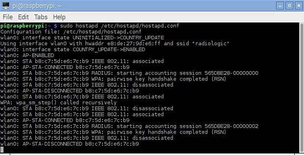
WLAN-Host messages for two connections and disconnections with an iPad

WLAN-Host messages for two connections and disconnections with an iPad

hostapd can be terminated by pressing simultaneously the keys  “Ctrl” and “c” .

To start hostapd at boot, we need to do some additional tasks. First we must uncomment and complete the parameter DAEMON_CONF in the file /etc/default/hostapd as follows :

DAEMON_CONF="/etc/hostapd/hostapd.conf"

We need to insert the same parameter in the init file /etc/init.d/hostapd.

Next we enable starting of hostapd at booting with the command

sudo systemctl enable hostapd
Enable autostart of hostapd at booting

Enable autostart of hostapd at booting

The new systemctl command synchronizes the booting process with the old legacy sysvinit command using update-rc.d. After a reboot we can check the status of the hostapd service with the command

service hostapd status

or

systemctl status hostapd
Show status of the hostapd service

Show status of the hostapd service

The following commands are used to stop, start, restart or disable hostapd :

sudo systemctl stop hostapd
sudo systemctl start hostapd
sudo systemctl restart hostapd
sudo systemctl disable hostapd

Hostapd needs random data to encrypt the WLAN. In computing, the randomness of data is called entropy. When the entropy is too low, “Add randomness” messages are displayed.

entropy

Raspberry messages related to randomness (entropy)

The entropy level can be checked with the command

cat /proc/sys/kernel/random/entropy_avail

When the returned value is less than 1.000, the entropy is unsufficient for secure cryptographic processes, which is often the case in small systems like the Raspberry Pi. Fortunately there is a solution :  HArdware Volatile Entropy Gathering and Expansion (HAVEGE).

The HAVEGE project is an attempt to provide an easy-to-use, unpredictable random number generator based upon an adaptation of the HAVEGE algorithm. The havege module is installed with the command

sudo apt-get install haveged

Another critical point related to hostapd is the power-save feature of most WiFi dongles. While this is a strong advantage when the WiFi dongle is in infrastructure mode (outbound) where the device is reactivated by the user, this is a great risk in AP mode when the computer works headless. In power-save mode, the WiFi dongle is no longer accessible by an external client and the only solution is to reboot the computer by unplugging and re-plugging the power supply.

We can check the status of power management with iwconfig.
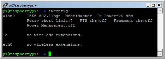
iwconfig

Check the power management status of the WiFi dongle with iwconfig

To prevent the Wifi dongle from entering the power-save mode, we can add the command

wireless-power off

in the /etc/network/interfaces file.

Another possibility is to create configurations files in the directory /etc/modprobe.d/.

Examples for Realtek drivers :

8188eu.conf

options 8188eu rtw_power_mgnt=0

8192cu.conf

options 8192cu rtw_power_mgnt=0

Networking setup

Until now, the WiFi adapter has an auto-assigned IP address and the clients don’t receive an IP address when connecting to the WLAN, which is not a workable solution. We need a static IP address for wlan0 and a DHCP-server to attribute IP addresses to the WLAN clients.

Many tutorials about Raspberry Pi deal with static IP addresses to simplify the access to the RPI when the routing is managed by a DHCP-server. Most of them refer to the legacy ifupdown configuration file /etc/network/interfaces, which is obsolete with Raspbian Jessie using the DHCP-client dhcpcd developed by Roy Marples. The network configuration should be done in the file /etc/dhcpcd.conf. If a static IP address is required for the eth0 interface, a more simple way is to set it in the router of the local network. In my specific case this is a Fritzbox 7390. The best way however is to use the hostname of the Raspberry Pi to access it in the local network. The default hostname is raspberrypi. The hostname can be easily changed in the raspi configuration. The hostname is saved in the files /etc/hosts and /etc/hostnames.

The default configuration of /etc/network/interfaces to be used with dhcpcd is shown below:

# interfaces(5) file used by ifup(8) and ifdown(8)
# Please note that this file is written to be used with dhcpcd
# For static IP, consult /etc/dhcpcd.conf and 'man dhcpcd.conf'
# Include files from /etc/network/interfaces.d:
source-directory /etc/network/interfaces.d
auto lo
iface lo inet loopback
iface eth0 inet manual
allow-hotplug wlan0
iface wlan0 inet manual
wpa-conf /etc/wpa_supplicant/wpa_supplicant.conf

The content of the default configuration of the /etc/dhcpcd file is the following :

# A sample configuration for dhcpcd.
# See dhcpcd.conf(5) for details.
# Allow users of this group to interact with dhcpcd via the control socket.
#controlgroup wheel
# Inform the DHCP server of our hostname for DDNS.
hostname
# Use the hardware address of the interface for the Client ID.
clientid
# or
# Use the same DUID + IAID as set in DHCPv6 for DHCPv4 ClientID as per RFC4361.
#duid
# Persist interface configuration when dhcpcd exits.
persistent
# Rapid commit support.
# Safe to enable by default because it requires the equivalent option set
# on the server to actually work.
option rapid_commit
# A list of options to request from the DHCP server.
option domain_name_servers, domain_name, domain_search, host_name
option classless_static_routes
# Most distributions have NTP support.
option ntp_servers
# Respect the network MTU.
# Some interface drivers reset when changing the MTU so disabled by default.
#option interface_mtu
# A ServerID is required by RFC2131.
require dhcp_server_identifier
# Generate Stable Private IPv6 Addresses instead of hardware based ones
slaac private
# A hook script is provided to lookup the hostname if not set by the DHCP
# server, but it should not be run by default.
nohook lookup-hostname

The lo interface (loopback) serves communication with localhost and is started automatically at boot. The IP address for the eth0 interface is requested by dhcpcd and provided by the LAN-router. The configuration for the wlan0 interface is provided by the /etc/wpa_supplicant/wpa_supplicant.conf file.

The status of the dhcpcd client is requested with the command

sudo systemctl status dhcpcd
dhcpcd status

Status of the dhcpcd client

For the headless operation of the Raspberry Pi with a WLAN Access Point I use a minimal network configuration :

/etc/network/interfaces

# Legacy interface (ifupdown) file used with dhcpcd
auto lo
iface lo inet loopback
iface eth0 inet manual

/etc/dhcpcd.conf

# DHCPCD configuration
hostname
clientid
persistent
option rapid_commit
option domain_name_servers, domain_name, domain_search, host_name
option classless_static_routes
option ntp_servers
require dhcp_server_identifier
slaac private
nohook lookup-hostname
interface wlan0
inform 192.168.123.1
static routers=192.168.123.1

A static IP address (192.168.123.1) can be attributed to wlan0 by means of the WiFi Network Panel opened by right clicking the WiFi icon in the task bar.
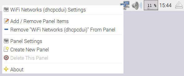
WiFi

WiFi Popup Menu to manage panels

The data inserted in the WiFi Networks Settings are saved in the /etc/dhcpcd.conf file as shown above.
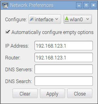
Wifi

Network preferences wlan0 interface options

DNSMASQ

One piece of the puzzle is still missing : a Dynamic Host Configuration Protocol (DHCP) Server to provide IP addresses to the WLAN clients. There are several dhcp-server packages available for Raspbian. I selected dnsmasq, a very useful module to set up a complete WLAN router. dnsmasq is a Domain Name System (DNS) forwarder and a DHCP-server for small computer networks, which are easily configurable, with low usage of system resources.

dnsmasq is installed with the command

sudo apt-get install dnsmasq

The configuration is done in the file /etc/dnsmasq.conf. Here is a link to the content of the default dnsmasq.conf file. My minimal configuration is the following :

# DNSMASQ Configuration
interface=wlan0
no-dhcp-interface=eth0
dhcp-range=192.168.123.2,192.168.123.99,12h

The DHCP-server is restricted to the wlan0 interface, the eth0 interface is excluded. The range of IP addresses to attribute to the WLAN clients is bounded by 2 and 99 in the sub-network 192.168.123.0. The lease time is 12 hours.

dnsmasq is managed with the same type of commands as hostapd :

sudo systemctl start dnsmasq
sudo systemctl stop dnsmasq
sudo systemctl restart dnsmasq
sudo systemctl enable dnsmasq 
sudo systemctl disable dnsmasq 
sudo systemctl status dnsmasq
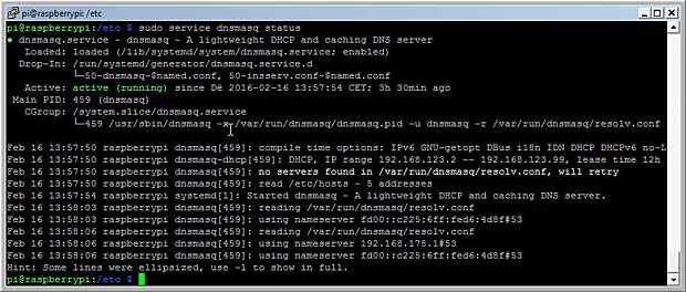
DNSMASQ

Status of the dnsmasq server

To test the correct access with WLAN clients to the Raspberry Pi, we will use the installed web-server lighttpd. The configuration files for the web-server are located in the directory /etc/lighttpd/. The web pages are located in the folder /var/www/html/. By entering the URL

http://192.168.123.1

in a browser after logging into the radiologic WLAN, we can display the index web page. A screenshot of the default html index page is shown hereafter :
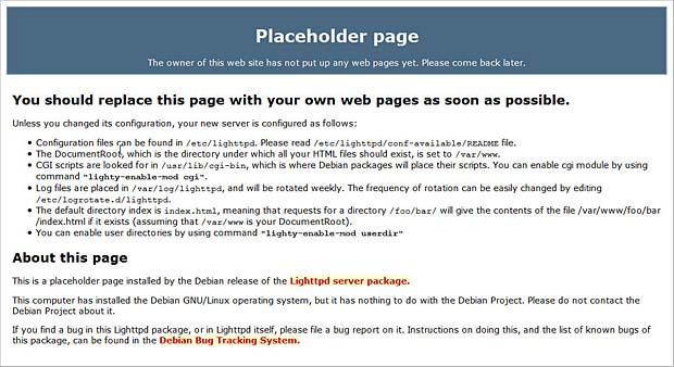
Default web

Default web page of the lighttpd web server

I replaced this page with the following minimal html script :

<!DOCTYPE HTML>
<html>
<head>
<meta http-equiv="Content-Type" content="text/html; charset=utf-8">
<title>Welcome Page</title>
<style type="text/css">
h1, h3 {text-align:center}
</style>
</head>
<body>
<h1>Welcome</h1>
<h3> to the Rasperry Pi WLAN</h3>
</body>
</html>

The following photo shows the result on various mobile devices accessing the radiologic WLAN.

iPad, iPhone, Samsung, LG and Blackberry mobile devices conncetd to the Blackberry Pi WLAN

iPad, iPhone, Samsung, LG and Blackberry mobile devices connected to the RPi WLAN

Currently the clients can only access the embedded web server. If we want that the WLAN clients have access to the global Internet or to other services, we need to add more network configuration parameters or specific applications. This will be a topic of further contributions.

Service Management

As a last step we check that all programs are running without errors and that the performance of the system is correct. First we need to understand the boot process.

Debian separates the legacy boot process (based on System V init)  into seven runlevels labeled as 0, 1, 2, 3, 4, 5, 6 and S. For each runlevel a file rcx.d (x = 0, 1, 2, …) exist in the directory /etc/ containing symbolic links to targets located in /etc/init.d/. The runlevels are defined as follows :

  • 0 : (halt) stop all services and make the system ready for shutdown
  • 1 : (minimal mode) stop all services and put the system in single-user rescue mode
  • 2 – 4 : multiuser network enabled text mode
  • 5 : multiuser network enabled graphical mode
  • 6 : (reboot) stop all services, make the system ready for reboot
  • S : (single) these scripts are executed once

When we enable a service to auto-start, we are adding it to a runlevel.

Default Debian installation does not make any difference between runlevels 2-5. Number 2 is the default runlevel at start. In a normal boot the levels progress up to 5. Runlevels S  and 1 are used for maintenance. Runlevels can be edited manually by editing control scripts in /etc/init.d and symbolic links in /etc/rc0.d … /etc/rc6.d. The runlevel can also be changed at runtime with the command telinit [runlevel 2-5]. The current runlevel is indicated with the command runlevel.

Looking at the list of the services included in the /etc/init.d/ folder, we discover among others the installed programs dnsmasq, dhcpcd, haveged, hostapd and lighttpd.
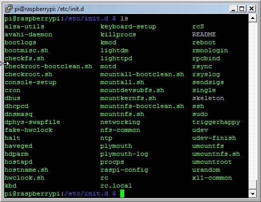
init.d

Content of the folder /etc/init.d/

Here is an extract from the init.d README file :

BEGIN INIT INFO
# Provides: skeleton
# Required-Start: $remote_fs $syslog
# Required-Stop: $remote_fs $syslog
# Should-Start: $portmap
# Should-Stop: $portmap
# X-Start-Before: nis
# X-Stop-After: nis
# Default-Start: 2 3 4 5
# Default-Stop: 0 1 6
# X-Interactive: true
# Short-Description: Example initscript
# Description: This file should be used to construct scripts to be
# placed in /etc/init.d.
### END INIT INFO

For each program defined as script in the /etc/init.d/ folder we can specify the runlevels for start and stop and the dependencies with other programs. The next figure shows a real example of an init-script related to the dnsmasq service :
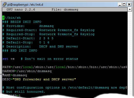
init.d dnsmasq

init script related to dnsmasq in the /etc/init.d/ folder

We see that the virtual boot facilities $network, $remote_fs and $syslog must be started or stopped before the dnsmasq service. Creating init scripts manually is an error-prone task. For this reason the legacy System V (SysV) init program has now been replaced by new init systems. Raspbian Jessie is using systemd as service manager. We have already seen the related tool systemctl to start, stop, enable and disable programs.

In systemd, the targets of most actions are units, which are resources that systemd knows how to manage. Units are categorized by the type of resource they represent and they are defined with unit files. The systemd files are located in the directories /lib/systemd/system/ and /etc/systemd/system/.

Some useful systemd commands are listed below :

systemctl is-active application.service
systemctl is-enabled application.service
systemctl is-failed application.service
systemctl list-units
systemctl list-units --all
systemctl cat application.service
systemctl list-dependencies application.service
systemctl show application.service
sudo systemctl mask application.service
sudo systemctl unmask application.service
sudo systemctl edit application.service
systemctl get-default

For most commands the .service suffix can be omitted. Some real commands concerning hostapd are shown in the next figure :
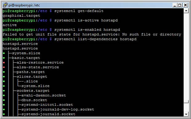
results of some systemd systemctl commands

Results of some systemctl commands for hostapd

systemd has some great built-in tools to check and tune the boot time. The commands

systemd-analyze
systemd-analyze blame

will print the boot time respectively print the list of the most time-consuming services in decreasing order.
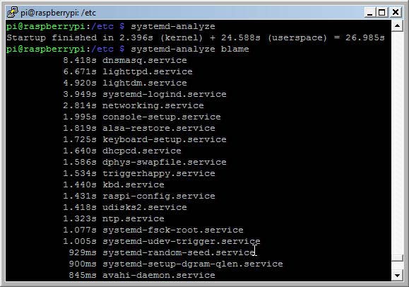
systemd-analyze results

systemd-analyze results

The command

systemd-analyze plot > init_plot.svg

creates an xml svg file which can be rendered in a browser. It displays in a graphical way when all the services start.
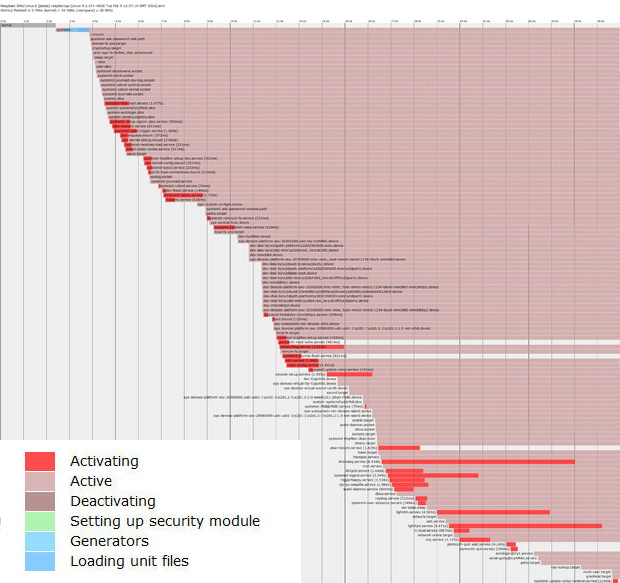
init_plot.svg file rendered in browser; click to enlarge

init_plot.svg file rendered in browser; click to enlarge

systemd has also a powerful tool to view and manipulate system logs named journald. The related configuration file is located in /etc/systemd/journald.conf. Some useful commands are :

journalctl
journalctl --all 
journalctl --since=yesterday

journald provides various filters using time constraints. Logs can be viewed in UTC or local time at will. The following journald commands deal with time and date.

timedatectl list-timezones
sudo timedatectl set-timezone zone
timedatectl status
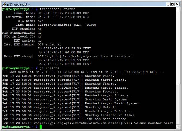
journalctl

systemd tools : timedatectl and journalctl

journald provides other filter options than time constraints : units, users, groups, processes, pathes, priorities, … The journal display can be customized in various formats. The amount of space occupied by the journal on the SD card can be shown with the the command

journalctl --disk-usage

Backup and Cloning

When a bad shutdown has corrupted the file system, the Raspberry Pi can be a frustrating experience. It’s therefore useful to wait for the complete shut down of the RPi before unplugging the power supply. To shutdown or reboot the Raspberry Pi, we can use the menu “Shutdown” in the VNC-desktop
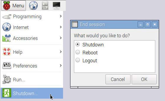
Shutdown

End Raspberry session with shutdown, reboot or logout

or the commands

sudo shutdown
sudo reboot

It’s also important to make at regular times a backup of the Raspberry Pi SDcard. Backups are possible on Windows 7 systems (or later) with the Win32DiskImager tool. First an image of the source card is saved to a file on the Windows PC. In an second step this image is copied to a backup SDcard. Backup’s can also be done with the Raspberry Pi itself by using an SDcard reader with USB interface.

Cloning a SDcard is the same procedure as doing a backup, but the goal is different. Cloning allows to distribute a complete mirror of a working RPi system with operating system, applications and data. This way it’s easy to copy and multiply an existing solution.

Sometimes a cloned image file can’t be copied to an SDcard with the same capacity, because SDcards can vary a little bit in size. There are several tutorials on the net how to solve this problem by shrinking the image file, for example one by Andrew Aokley, another one on the Wonky Gibbon Ramblings Blog.

I used the following procedure on my Debian computer :

df -h
cd /home/mbarnig/Desktop/
sudo dd if=/dev/sdb2 of=myimage.img bs=4M
sudo dd if=myimage.img of=/dev/sdb2 bs=4M conv=notrunc,noerror

Links

The following list provides links to websites with additional informations about the Raspberry Pi :

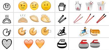
Digital Imaging

Last update: February 12, 2017

Digital imaging is the creation of digital images, such as of a physical scene, and includes the processing, compression, storage, printing, and display of such images. The information is converted by image sensors into digital signals that are processed by a computer. If the medium which conveys the information that constitutes the image is visible light, it’s called digital photography.

Photosensor Array

A digital camera or a scanner uses an array of photosensors (photosites) to record and store photons. Once the exposure finishes, the relative quantity of photons in each photosite is then sorted into various intensity levels, whose precision is determined by bit depth (0 – 255 for an 8-bit image).

One photosensor per image pixel would only create grayscale pictures. To capture color images, distinct photosensors are necessary for each of the three primary colors (RGB). To separate the colors, a filter array is placed over each photosensor. The most common type of color filter array is called a Bayer Array, as shown in the figure below.

credit

image credit : www.cambridgeincolour.com

A Bayer Array consists of alternating rows of red-green and green-blue filters. Because the human eye is more sensitive to green light than both red and blue light, the Bayer Array contains twice as many green as red or blue sensors to approximate the human vision.

Dynamic Range

When speaking about dynamic range, we need to distinguish between recordable or displayable dynamic range. Let’s start with the first one.

The Dynamic Range in digital imaging describes the ratio between the maximum (white) and minimum (black) measurable light intensities. The black level (few photons) is limited by noise. The white level (large number of photons) is limited by overflow (saturation). If an ideal photosensor identifies one photon for black and hosts a maximum of 1.000 photons (white), the dynamic range would be 1.000:1. The most commonly used unit for measuring dynamic ranges in digital photography is the f-number (f-stop) which describes the total light range by powers of 2. A dynamic range of 1.000:1 is therefore equivalent to 10 f-stops (2 exp 10 = 1.024). In scanners the dynamic range is described in terms of density (D). Density is measured using powers of 10. A dynamic range of 1.000:1 is represented by a density of 3 (10 exp 3 = 1.000). As a scanner has full control over it’s light source, such a device can ensure that minimal photosensor overflow occurs.

The approximated dynamic range in f-stops for several devices is indicated below :

recordable displayable
  • human eye : 24
  • scanner : 8 – 12
  • digital camera : 5 – 9
  • monitor display : 6 – 11
  • printed media : 2 – 7

ISO sensitivity

How much light is needed to saturate a medium is determined by it’s sensitivity. That was as true for glass plates as it was for film and now for digital photosensors. The sensitivity (film speed) is expressed in ISO. The normal range of ISO is about 200 to 1.600, but can sometimes go as low as 50 or as high as 204.800.

Image Bit Depth

Bit depth quantifies how many values are available to specify each image pixel. Even if a digital imaging system can capture a vast dynamic range, the light measurements must be translated into discrete numerical values with an analog to digital (A/D) converter. With 8 bits per color channel, the dynamic range cannot exceed 8 f-stops (density of 2.4) if the numerical values are linearly interspaced. With 16 bits per color channel, the theoretical value for the dynamic range in an ideal linear system would be 16 f-stops (densitiy 4.8). In practice the dynamic range of a linear system is much lower, even with 16 bits (typically about 12 f-stops). If we use however an nonlinear system to interspace and save the discrete numerical values, we could even conceive to record an infinite dynamic (posterized) range with an image depth of a few bits.

RAW image

At the end of the A/D conversion, we have a raw digital image, with W x H pixels, specified with consecutive discrete numerical values, each value coded with N bits per color channel. Each camera manufacturer and each scanner software developer uses a proprietary format for a raw digital image. A common format called Digital Negative (DNG) has been defined by Adobe in 2004.

Image Histograms

Image histograms are great tools to evaluate the correct exposure of a captured digital image.

Each pixel in the raw image is specified by the primary colors red, green and blue (RGB). Each of these colors can have a brightness value ranging from 0 to X ( X = 2 exp N ). A histogram results when the computer scans through each of the brightness values and counts how many are at each level from 0 through X. Low brightness values are called shadows, high values are the highlights, in-between are the midtones.

histogram

Histogram

A well balanced histogram where no shadows or highlights are clipped is shown at left. The region where most of the brightness values are present is called the tonal range. When highlights are heaped at the right edge in the histogram, they are clipped (blown). Some regions in the image have been overexposed and the corresponding details can never been recovered.

When shadows are heaped at the left edge in the histogram, some regions of the image have been underexposed and the relevant dark details are also lost. The histogram of a raw digital image should not present high values at the left (shadows) and right (highlights) edges of the chart. If clipping occurs you see a tall vertical line at the far left or right side of the histogram.

Usually an image is underexposed if no channel of the histogram goes all the way to the right. Images that are too dark are easy to correct later in this case; just drag the right slider in Photoshop’s Levels command to the left to meet the edge of the histogram.

The distribution of peaks in a histogram depends on the tonal range of the subject. Images where most of the tones occur in the shadows are called low key, whereas in high key images most of the tones are in the highlights. The histogram describes also the contrast which is the measure of the difference in brightness between dark and light areas in an image. Broad histograms reflect a significant contrast, narrow histograms present low contrast resulting in flat (dull) images.

All histograms are normalized and are intentionally scaled so that the top of the tallest peak always reach full height. Scale is relative, shown percentage-wise.

There exist three types of image histograms :

  • Color Histograms
  • RGB Histograms
  • Luminosity (Luminance) Histograms

Each histogram type has it’s own use and it’s own shortcomings. All three should be used as a collective tool. The following figures show the different histograms relative to a scanned Kodachrome slide of a landscape.

Landscape

Scanned Kodachrome slide of a landscape

Photoshop histogram windows

Landscape photo histogram windows RGB, R, G, B, Luminosity and Colors in Photoshop

Color Histograms

A color histogram describes the brightness distribution for any of the three primary color channels R, G, B. This is helpful to assess whether or not individual colors have been clipped.

Sometimes color histograms are presented as color overlays (colors histogram).

RGB Histograms

An RGB histogram produces three independent histograms for each color channel and then adds them together, irrespective of whether the color came from the same pixel. This way RGB histograms discard the location of each pixel.

Luminosity (Luminance) Histograms

The terms luminosity and luminance are often used interchangeably, even though each describes a different aspect of light intensity. Technically the term luminosity is correct and I will use it in the following, even if luminance is more common. The luminosity histogram takes into account that our eyes are most sensitive to green; we see green as being brighter than we see blue or red. Luminosity weighs the effect of this to indicate the actual perceived brightness of the image pixels based on the NTSC television formula

Luminosity = Red x 0.3 + Green x 0.59 + Blue x 0.11

Color Models

Until now we have used the terms primary colors (RGB), color channels, color and colors histograms, luminosity, luminance, light intensity, brightness, but we never really dealt with colors.

The search for a comprehension of exactly what color is and how it functions has been going on for hundreds of years. Artists and philosophers have theorized that color is three-dimensional. Contemporary neuroscientists have confirmed this theory, finding that our sensation of color comes from nerve cells that send messages to the brain about:

  • The brightness of color
  • Greenness versus redness
  • Blueness versus yellowness

Numerous models and systems have been developed :

There are several ways to associate the converted discrete numerical values of the primary color channels R, G, B to colors. We can rely on the physics of light waves (visible spectrum), on the characteristics of inks, dyes, paints or pigments, on the human eye or visual perception. In all cases we need a color model as reference to process (adjust)  the discrete numerical values.

Wikipedia defines colors and color models as follows :
Color (American English) or colour (Commonwealth English) is the visual perceptual property corresponding in humans to the categories called red, blue, yellow, etc.”
A color model is an abstract mathematical model describing the way colors can be represented as tuples of numbers, typically as three or four values or color components.”

The ICC defines colors as :
Color is the sensation produced in response to selective absorption of wavelengths from visible light. It possesses the attributes of Brightness, Colorfulness and Hue. White, grey and black are achromatic colors.

My personal definition of color in digital imaging is the following :
Color is the tone displayed when the numerical values of the three color channels are not all the same. This implies that black, white and all grey tones are not colors.”

This personal definition is consistent with all what has been said up to now in this post. With an image bit depth of 8 bits, 256 x 256 x 256 = 16.777.216 different colors and grey tones can be specified (in theory).

The color models used today are the following :

  • RGB (ca 1860) : Additive Color Model ( Red + Green + Blue = white)
  • CMYK (ca 1906) : Subtractive Color Model (Cyan + Magenta + Yellow = brown; + K = Black)
  • LAB (1948) : developed by Richard S. Hunter
  • NCS (1964) : Natural Color System
  • HSV (1978) : Hue, Saturation and Value (Alvy Ray Smith)
  • HSL (1978) : Hue, Saturation, and Lightness (Alvy Ray Smith)
  • HWB (1996) : Hue, Whiteness, Blackness (Alvy Ray Smith)
Main color models : RGB, CMYK, Lab

Main color models : RGB, CMYK, Lab

The most common color model is RGB. The following figure shows the RGB cube with the 3D representation of all possible (in theory) colors and grey-tones, including black (R = G = B = 0) in the back lower corner and white (R = G = B = max) in the front upper corner.

RGB cubes

RGB cube

RGBA is a RGB color model with and additional alpha (opacity) channel. There is an open ended set of RGB spaces; anyone can invent one by picking new primaries and a gamma value. Some color spaces are commercial ones and copyrighted, some are defined for special purposes and some are obsolete.

Typically used in color printing, CMYK assumes that the background is white, and thus subtracts the assumed brightness of the white background from four colors: cyan, magenta, yellow, and black. Black is used because the combination of the three primary colors (CMY) doesn’t produce a fully saturated black. You should however be aware that some desktop printers have only an RGB interface. Some printers use special premixed inks called Spot Colors.

The Natural Color System (NCS) is a proprietary perceptual color model based on the color opponency hypothesis of color vision, first proposed by Ewald Hering. The current version of the NCS was developed by the Swedish Colour Centre Foundation.

HSV and HSL have been developed in 1978 by Alvy Ray Smith, a pioneer in computer graphics and cofounder of the animation studio Pixar. They are used today in color pickers. The two representations rearrange the geometry of RGB in an attempt to be more intuitive and perceptually relevant than the cartesian (cube) representation. The colors are represented in a cylindrical coordinate system. Twenty years later Alvy Ray Smith created HWB to address some of the issues with HSV and HSL. HWB came to prominence in 2014 following its use in the CSS Level 4 Color Module.

In contrast to color models which define a coordinate space to describe colors, the Color Apperance Model (CAM) is a mathematical model that seeks to describe the perceptual aspects of human color vision.

Color Spaces

A color space is a specific implementation of a color model. The physical colors represented in the coordinate space (cube, cylinder) of a color model are not all visible by humans. For this reason the International Commission on Illumination (CIE) defined in 1931 quantitative links between physical pure colors (wavelengths) in the electromagnetic visible spectrum and physiological perceived colors in human color vision. These links are represented as 3D regions (3D solids) containing all producible colors, called the CIE 1931 color space. The CIE 1931 color space standard defines both the CIE 1931 RGB space, which is an RGB color space with monochromatic primaries, and the CIE 1931 XYZ color space, which works like an RGB color space except that it has non-physical primaries that cannot be said to be red, green, and blue. The CIE standards are based on a function called the standard (colorimetric) observer, to represent an average human’s chromatic response.

3D Color Space

Color Space : different vues of the 3D solid representing visible colors

Visualizing color spaces in 3D is not very easy and intuitive. For this reason color spaces are usually represented using 2D slices from their full 3D shape. Unless specified otherwise, a 2D chromacity diagram shows the cross-section containing all colors which are at 50% luminosity (luminance). The next figure shows the CIE 1931 XYZ color space in two dimensions.

CIE 1931 XYZ color space

CIE 1931 XYZ color space at 50% luminosity (mid-tones)

The CIE defined additional standards for color spaces for special purposes like TV, video, computer graphics. A list is shown below :

CIE color spaces : XYZ, Lab, Luv

CIE color spaces : CIEXYZ, CIELAB, CIELUV

Gamuts

It’s good to know that the CIE XYZ color space encompasses all color sensations that an average person can experience, but it’s more important to know the subsets of colors that a given digital device can handle and reproduce. Such a portion of the CIE XYZ color space is called a device color space or gamut. The term gamut was adopted from the field of music, where it means the set of pitches of which musical melodies are composed. The following figure shows typical gamuts for some digital devices.

Typical gamuts of digital devices

Typical gamuts of digital devices with 50% luminosity

Keep in mind that this representation only shows mid-tones with 50% luminosity. When colors are dark or light, we perceive less variation in their vividness. We see the maximum range of color saturation for middle-toned colors. This is why the 2D slices of color models are usually represented with 50% luminosity. If we are interested in the color gamuts for the shadows or highlights, we could look instead at a 2D slice of the color space at about 25% and 75% luminosity.

The following figure shows the gamuts of real devices, the iPad 2 and iPad 3.

Gamuts of iPad 2 and iPad 3

Gamuts of iPad 2 and iPad 3

Color Transformation

Color transformation (color space conversion) is the translation of the representation of a color from a source color space to a target (destination) color space.

Out of

Out of

A typical use case is to print on an inkjet printer in the CMYK space a photo captured with a camera in the RGB color space. The printer gamut is different than the camera gamut, certain camera colors cannot be reproduced with the printer. Those colors are said to be out of gamut.

During the color transformation process, the RGB colors out of gamut must be converted to values within the CMYK gamut. This conversion is called gamut mapping. There are several reasonable strategies for performing gamut mapping, these are called rendering intents. Four particular strategies were defined by the International Color Consortium (ICC), with the following names:

  • Absolute Colormetric
  • Relative Colormetric
  • Perceptual
  • Saturation

If a complete gamut mapping is not possible, a gamut mismatch results and the best approximation is aimed. An interactive Flash demo explaining color gamut mapping is available at the website of the Stanford University.

In digital image edition programs (for example Adobe Photoshop), device independent color spaces, called working spaces, are used as a reference for the device-dependent gamuts. Working color spaces are color models that are well suited to image editing tasks such as tonal or color adjustments. The most important working spaces are listed below :

sRGB is sort of common denominator and used as default for unmanaged computers. This color space is appropriate for uploading images to the web and to send them for printing to minilabs if no custom space is specified. It has been endorsed by the W3C and by many industry leaders. sRGB is not well suited as working space because it has a narrow gamut.

Usually the input and output color spaces are smaller than the working color space.

Color temperatures

Color temperature is another characteristic of visible light that is important in digital imaging and photography. Color temperature is conventionally stated in the unit of absolute temperature, the Kelvin, having the unit symbol K. Color temperatures over 5.000K are called cool colors, while lower color temperatures (2.700–3.000 K) are called warm colors.

The color temperature of sunlight above the atmosphere is about 5.900 K. Tungsten incandescent lamps used formerly in the photography had a temperature of 3.200 K. The CIE introduced in 1931 the concept of the Standard Illuminant, a theoretical source of visible light. Standard illuminants provide a basis for comparing images or colors recorded under different lighting. Each of these is defined by a letter or by a letter-number combination.

Fluorescent lighting adds a bluish cast to photos whereas tungsten lights add a yellowish tinge to photos. Humans don’t generally notice this difference in temperature because our eyes adjust automatically for it. The process in digital system to compensate these color casts is called white balance. The goal is to correct the lighting so that white objects appear white in images. White balance can be done automatically or manually. Two standard white points are used in white balance : D50 and D65.

In digital imaging, it is important to know a monitor’s color temperature. Common monitor color temperatures, along with matching standard illuminants, are as follows:

  • 5.000 K (D50)
  • 5.500 K (D55)
  • 6.500 K (D65)
  • 7.500 K (D75)

The spectrum of a standard illuminant, like any other profile of light, can be converted into tristimulus values. The set of three tristimulus coordinates of an illuminant is called a white point and can equivalently be expressed as a pair of chromaticity coordinates.

Color Profiles

Informations about device gamuts and illuminants are registered in ICC profiles. ICC is the International Color Consortium which was formed in 1993 by eight vendors in order to create an open, vendor-neutral color management system which would function transparently across all operating systems and software packages. Every device that captures or displays color can be profiled. A profile can be considered as a description of a specific color space.

Profiles describe the color attributes of a particular device or viewing requirement by defining a mapping between the device source or target color space and a profile connection space (PCS, either CIEXYZ or CIELAB) serving as reference.There are two types of profiles :

  • matrix-based : mathematical formulas
  • table-based : large tables of sample points (LUT = look up table) to define the 3D color space

Mappings may be specified this way using tables, to which interpolation is applied, or through a series of parameters for transformations.

ICC profiles help you to get the correct color reproduction when you input images from a camera or scanner and display them on a monitor or print them.

Color

Color conversion with ICC profiles

An ICC profile must conform to the ICC specification. The latest profile version is 4.3.0.0, the corresponding specification ICC.1:2010-12 is technically identical to the ISO standard 15076-1:2010.

There are different device classes of profiles : input, output, display, link, abstract, colorspace, … ICC profiles may have the suffix .icc or .icm. Display profiles are commonly of the Matrix/TRC type with a 3×3 matrix of the colorant primaries tristimulus values and a one-dimensional tone curve for each colorant. They can also be of the multi-dimensional look-up table (LUT) type with a three-dimensional look-up table and a second one-dimensional tone curve. Some device-independant profiles are purely theoretical and describe a way to turn color into numbers. Others are device-dependant and describe the color signature of a particular device.

A profile does not correct anything in the image. An original with a color cast (Farbstich) keeps the cast during the color conversion. Image correction and cast removals are separate processes which need specific software.

ICC profiles can be embedded in digital images, for example in JPEG files. If the profile uses a standard color space like sRGB, a simple EXIF tag is sufficient to indicate it. If a custom (non-standard) color space is used, the complete data segment can be embedded. Photoshop features check-boxes to embed ICC profiles in dialog boxes when saving or creating images.

A free program for Windows to view the content of ICC profiles has been developed by Huan (Huanzhao) Zeng. The software is called ICC Profile Inspector; the current version 2.4.0 was updated on February 22, 2009. The following figure shows a screenshot of the program displaying the header and the tag table of the Blurb ICC Profile for Blurb books.

ICC Inspector

ICC Profile Inspector showing the Blurb book ICC profile

The device class of the Blurb ICC profile is output, the color space is CMYK, the profile connection space is Lab, the rendering intent is relative colormetric and the illuminant has the values X = 0.9642, Y = 1.0, Z = 0.82491. AToBn (A2Bx) and BToAn (B2Ax) are gamut mapping tables used in printer profiles. A refers to the device, B to the profile connection space. A2B tags are used for proofing, B2A tags are used for printing.

By clicking on a tag in the ICC Profil Inspector, the corresponding content is displayed.

The next figure shows a screenshot of the program displaying the header and the tag table of my Sony Vaio laptop :

sony_srgb

ICC Profile Inspector showing the ICC profile of a labtop display

The device class of the Sony ICC profile is display, the color space is RGB, the profile connection space is XYZ, the rendering intent is perceptual and the illuminant has the values X = 0.96419, Y = 1.0, Z = 0.82489. The tags rXYZ, gXYZ and bXYZ present the gamut for the three channels, the tag wtpt shows the white point, the tags rTRC, gTRC and bTRC indicate the Tone Response Curves for the three channels in 16bit mode (see gamma encoding later in this post).

ICC

ICC color profile  for Sony Vaio labtop display : gamut, white point, gamma

Windows Color Management panel allows to change settings for the ICC profiles. Mac OS X has an inbuilt ICC profile inspector inside the umbrella application ColorSync Utility.

An OpenICC project was launched in 2004. Files are available at Sourceforge.

RAW to JPEG / TIFF conversion

To view our image, we must display it on a monitor or print it on paper. In both cases we need to process (edit) the image to cope with limitations of the output medium and with another particularity of the human vision. Compared to a photosensor, our eyes are much more sensitive to changes in dark tones than we are to similar changes in bright tones.

A standard computer monitor can only display 8 bits per color channel. The common image file formats used in this environment are compressed JPEG or uncompressed TIFF files. To convert our raw image into on of these standards, we need to apply several image adjustments; some are irreversible. Often these adjustments are done automatically inside the digital imaging system (camera, scanner), but it’s also possible to do it manually outside with an image editing software like Photoshop.

The steps to adjust the digital image are the following :

  • Demosaicing
  • Gamma encoding
  • White Balance
  • Tonal compensation
  • Color Compensation
  • Sharpening
  • Compression

Demosaicing

Let’s come back to our photosensors without considering their dynamic range, sensitivity or bit depth. To create a color image from the captured photons in the photosensors, a first process is the Bayer Demosaicing to provide full color information at each image pixel. Different demosaicing algorithms are applied to improve the image resolution or to reduce the image noise. Small-scale details in images near the resolution limit of the digital sensor can produce visual artifacts, the most common artifact is Moiré.

Gamma encoding

To translate between our eye’s light sensitivity and that of a digital imaging system, a function called gamma is used. In the simplest case the nonlinear gamma function is defined by the following power-law expression:

Vout = A * Vin exp gamma

Vout and Vin are the input and output luminositye values, A is a constant (usually A = 1) and gamma is the exponent. A gamma value lower than 1 is called an encoding gamma, a value greater than one is a decoding gamma. In the first case the compressive power-law nonlinearity is called gamma compression; conversely the application of the expansive power-law nonlinearity is called gamma expansion. The term gamma correction is sometimes used for both processes.

We distinguish three types of gamma :

  • Image Gamma
  • Display Gamma
  • System Gamma

The image gamma is applied on the raw image data before converting them to a standard JPEG or TIFF file and saving it to the memory card. The gamma encoding redistributes the native tonal levels into ones that are perceptually more uniform, making a more efficient use of a given bit depth. The encoding gamma is usually about 1 / 2.2 = 0.455.

The display gamma refers to the video card and monitor and compensate for the image gamma to prevent that the image is displayed too bright on the screen. The display gamma is usually equal to 2.2.  On old Mac computers the value was 1.8.

The system gamma (viewing gamma) is the net effect of all gammas applied to the image. The system gamma should ideally be close to 1, resulting in a straight line in the gamma chart.

The following figures shows the three gamma plots :

Gamma charts

Gamma charts image, display and system

The precise gamma is usually specified by the ICC color profile that is embedded within the image file. If no color profile is indicated, then a standard gamma of 1/2.2 is assumed.

Tone and color adjustment

We should now have a good understanding about colors, but we didn’t yet explained what are tones. Are tones synonymous to brightness ? Some specialists refer to musical allusions to define tones. Other say that tones include colors. Years ago in a photo forum it was stated that there are only two terms needed to specify tones and colors : hue and luminosity. Ken Bhasin concluded in this forum : “Tone is the degree of greyness. If the subject has color, imagine taking away its color – what remains is its tone. Absence of any tone makes a subject bright (light grey/white). Presence of a tone makes a subject dark (Dark grey/black).” I endorse this definition.

There are several tools to adjust or correct tones and colors. Most are interrelated and influence both tones and colors. The most common tools are presented hereafter with reference to the Photoshop software.

Levels is a tool which can move and stretch the levels of an image histogram. It adjust brightness, contrast and tonal range by specifying the location of complete black, complete white and midtones in a histogram.

The following example shows two Kodachrome slides scanned with a cheap diascanner Maginon FS6600.

Scanned Kodachrome portrait with histograms

Scanned Kodachrome portrait with histograms

The histograms of the three color channels indicate an underexposure.

Color adjustment with Levels Tool in Photoshop

Color adjustment with Levels Tool in Photoshop

By moving the white point to the left in the R, G and B histograms in Photoshop the levels are adjusted. Holding down the ALT-key while dragging the black or white slider is a trick to visualize shadow or highlight clipping and avoid it.

Adjusted portrait

Adjusted portrait

Because the levels have been modified differently in the three color channels, the adjustment influenced also the hue of the image.

Photoshop curves tool

Photoshop curves tool (non-sense adjustment)

A second tool is the Photoshop curves. It’s a very powerful and flexible image transformation utility. Similar to Photoshop levels, the curves tool can take input levels and selectively stretch or compress them. A curve is controlled using up to a total of 16 anchor points. The left figure shows an example of an (artistic nonsense) curve applied to the preceding portrait. The curves tool only redistributes contrast and allow us to better utilize a limited dynamic range. You can never add contrast in one tonal region without also decreasing it in another region. You must decide how to spend your contrast budget. Curves also preserves the tonal hierarchy, unless there are negative slopes in it. The following figure shows the resulting modified image.

Portrait

Portrait modified in Photoshop with the Curves Tool based on nonsense points


Curves can also be used on individual color channels to correct color casts (Farbstiche) in specific tonal areas. A typical example of digital images with color casts are scanned film negatives which have a strong orange mask. The reason an orange mask was added to color negative films was because of imperfections in the cmy dyes.

Scanned film negative with orange color cast and inverted into a positive

Scanned film negative

The orange color cast becomes purple when the image is inverted to a positive. All film scanning software comes  with color negative options. Typically a variety of color negative film types, such as Kodak Gold 100, Agfa, Fuji etc are listed in the scanner software. A good scan should avoid clipping in all the color channels, which can be easily checked in the histograms.

If the scanned image is not converted to a positive in the scanner, it can be done in Photoshop. The third Photoshop adjustment tool, called eyedropper (pipette), is well suited for this purpose. The eyedropper figures in the levels and curves panels (see figures above). The far left dropper tool is used to set the black point by clicking on a location within the image that should be black. The far right dropper tool does the same for the white point. The middle dropper tool sets the grey point which is an area in the image that should be colorless.

In a negative white and black are inverted. The lightest part of the negative (the darkest part of the scene) can be no lighter than the color of the base orange cast. If the orange cast can be converted to pure white in the negative (black in positive), then the remainder of the colors will be converted as expected. The next figure shows the areas where the eyedropper tool has been applied and the resulting inverted positive.

positive

Adjusted negative with the dropper (3 areas black, white, grey) and resulting positive

The global adjustment of the colors is called color balance. If the goal is to render specific neutral colors correctly, the method is called grey balance, neutral balance, or white balance respectively. General color balance changes the overall mixture of colors in an image and is used to get colors other than neutrals to appear correct or pleasing.

Photoshop offers various methods to automatize tone and color adjustments :

  • Auto Levels
  • Auto Contrast
  • Auto Color
  • Photo Filter
  • Special filters like ColorPerfect

Photoshop provides also various sliders to adjust manually the parameters color balance, brightness, contrast, hue, saturation, exposure, shadows, highlights etc. A great help is the Photoshop Variations Tools showing incremental changes of different parameters in images, with an indication of eventual clippings. The next figure shows variations of the portrait image for the shadows, mid-tones, highlights and saturation.

Photoshop Variations

Photoshop Variations

Another method to automatize color balance used by several image editors are selectors for  presets, for example :

  • landcsape
  • portraits, skin tones
  • night
  • beach
  • jewelry

Sharpening

The next step in the image processing workflow is sharpening. Resolution adds the detail that lets us recognize features. Sharpness makes edges clear and distinct. The standard tool of choice for sharpening is the UnSharp Mask filter (USM).

All color filter Bayer array algorithms, by definition, blur the image more than could have been theoretically captured by a perfect camera or scanner. Thats why sharpening is often integrated in the demosaicing process. If not, it can be done separately in an image editor like Photoshop.

Compression

A last step in the image processing workflow is compression to reduce irrelevance and redundancy of the image data in order to be able to store or transmit data in an efficient way. Image compression may be lossy or lossless.

The common image formats used in digital imaging today are JPEG and TIFF.

Color Management

Color management is the cross-platform view of all the features presented in the present post, based on ICC standards. Wikipedia defines color management in digital imaging systems as “the controlled conversion between the color representations of various devices. A color management system transforms data encoded for one device (camera, scanner) into that for another device (monitor, printer) in such a way that it reproduces the original colors. Where exact color matching is not possible, the result should be a pleasing approximation.”

Parts of the color management technology are implemented in the operating system (OS), for example ColorSync in Mac OS X and Windows Color System (WCS, formerly ICM) in Windows. Other parts are included in applications (for example Photoshop) and in devices (for example cameras). An open source color management called Little CMS (LCMS) was initiated by Marti Maria in 1998. LCMS is released under the terms of the MIT License as a software library for use in other programs which will allow the use of ICC profiles. The current version is 2.7, updated on March 17, 2015, available on Github.

One of the main components of a color management system is the Color Matching  Module (CMM), which is the software engine in charge of controlling the color transformations that take place inside the system. A Color Transformation Language (CTL) was created by the Academy of Motion Picture Arts and Sciences (A.M.P.A.S.) in 2007.
Besides the color profiles for devices and color spaces, the ICC has standardized a CMM. CMM’s are built into ColorSync and WCS. Photoshop is also a good example of a CMM.
Proper color management requires that all images have an embedded profile. Recent web browsers like Internet Explorer 9, Safari 6 or Firefox support color management.

Calibration

Profiling a device is called characterization. Instruments used for measuring device colors include colorimeters and spectrophotometers. Calibration is like characterization, except that it can include the adjustment of the device, as opposed to just the measurement of the device. When all device are calibrated to a common standard color space such as sRGB, no color translations are needed to get all devices to handle colors consistently. Monitors, scanners and printers are the common devices that can be calibrated.

Windows Display Calibration Tool

Windows Display Calibration Tool

Display Calibration Tool Adobe_gamma

Display Calibration Tool Adobe_gamma

Modern monitors include a factory-created profile that is loaded into the monitor firmware and is communicated to the computer. Some people prefer to replace these profiles with custom ones. Most operating systems include tools to calibrate the monitor. Adobe Gamma is a monitor calibration tool included in Photoshop.

Color charts such as IT8 are used to calibrate scanners. Printers should be calibrated for every type of paper and inks you use. One solution is to print a test chart and to scan it with a IT8 calibrated scanner. Scanner software like SilverFast calculates then an ICC profile for the printer and the paper and ink combination.

IT8 color chart

IT8 color chart

Photo Restoration

Digital photo restoration uses specific image editing techniques to remove visible damage, fading, color casts and other aging effects from digital copies of physical photographs. The most common tools are :

  • levels, curves, contrast and black level tools to remove fading
  • white balance, color balance and other color tools to remove color casts
  • clone stamp, healing brush and other selective editing tools to remove localized damage

Conclusions and recommendations

The human eyes and brain work together to create what we call vision. The eyes collect input and send it to the brain for processing. It’s the brain that decides what it is we see (or think we see). The brain makes its decisions based largely on perceived color and contrast data sent to it by the eye’s sensory elements such as cones and rods. Sometimes these decisions don’t match reality which can give rise to what we know as optical illusions. The human vision still performs better than the most complex digital imaging system.

Here are some rules based on the explanations given in the present post to guide you through the digital imaging process :

  • use Adobe RGB as a working space for 8 bit images and ProPhoto RGB for 16 bit images
  • assign the sRGB profile as default for unprofiled images
  • use a generic CMYK profile for printing if the printer does not supply a custom profile and if it’s not restricted to an RGB interface
  • use perceptual as default rendering intent; it’s the best choice for general and batch use and for images with intense colors
  • use relative colormetric rendering intent  for images with subtle tones (portraits); they benefit from the increased accuracy
  • apply the Photoshop Curves Tool only to 16 bit images

Links

A list with links to websites providing additional information about digital imaging is shown hereafter :

Electronic publishing platforms

Electronic publishing (e-publishing) includes the digital publication of e-books, digital magazines, and the development of digital libraries and catalogues.

One of the leaders in electronic publishing is Issuu, which was founded in Copenhagen, Denmark in 2006 by Michael Hansen, Ruben Bjerg Hansen, Mikkel Jensen, and Martin Ferro-Thomsen. Issuu is a digital newsstand with over 21 million publications and 85 million active readers, featuring titles in fashion, culture, arts, and more, all of which are accessible on any device. In 2014, issuu released Clip, a tool that allows readers to take a snapshot of any part of a publication and share that on social media or through email.

Here are some thumbnails of the magazines currently  available for reading at the Issuu platform :

Magazines on the electronic publishing platform Issuu

Magazines on the electronic publishing platform Issuu

The Current Master Volume 1 Publication by World Wide Art Books (WWAB) and related publications about art and culture are shown at the Issuu website. Some magazines are shown below :

Art Magazines on the electronic publishing platform Issuu

Art Magazines on the electronic publishing platform Issuu

Issuu offers a free basic account to start with the upload of own publications.